Left Controller
ID: 132760
Description:
Steps:
- Flip over the left controller and locate the four screws.
- Remove the four PH0 screws.
- Warning: A small ribbon cable connects the two halves of the controller, so be careful when opening.
- Warning: The two halves easily come apart, but the small ribbon cable between them can easily be damaged.
- Lift the back half slightly off the front half and fold it open along the left edge.
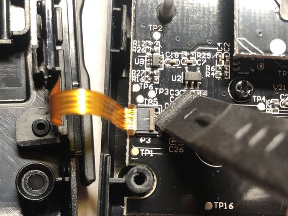
- The ribbon cable is circled in the second image.
- Use a plastic spudger to flip the ribbon cable latch up as shown in the first two images.
- Remove the ribbon cable from the slot by pulling gently to the left with tweezers or fingers.
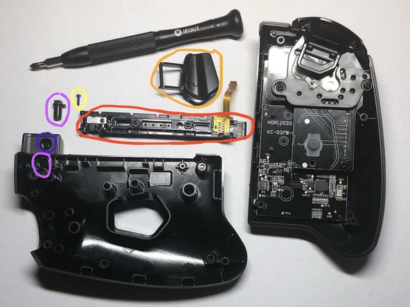
- Remove one PH00 screw that is securing the rail to the back half.
- The FL button can be removed by placing a lever/spudger under the circled area.
- The rail connector can be removed once the yellow circled screw is removed.
- The button that releases the buckle lock can be removed after the rail and goes in the hole circled on the back half of the controller.
- The one remaining screw does not need to be removed as it only secures a bit of plastic.
- Remove the three PH00 screws.
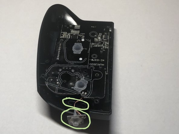
- Pry out the metal cover over the buckle lock. Be gentle so as not to bend the metal.
- The spring loaded buckle lock can then be removed. NOTE: Do not loose the spring when disassembling. Reassembly can be tricky because the spring needs to be compressed to get back in place.
- The plastic cover over the holes in the middle of the rail can be removed. This is where SL, SR, and connect buttons would be on a normal Joy Con controller and also the lights indicating which controller number it is.
- The ZL button can be removed once the red circled screws are removed.
- The L button is underneath the ZL button and is easily removed once the ZL button is out of the way. There is a small hole that one end of the L button fits into.
- Remove four PH0 screws, two that hold in the ZL button plastics and one on the top button board and one of the two screws securing the main motherboard.
- Warning: Do not try to remove the top button board before you remove this small button board in the next step.
- The small L button board is slid into a slot and has delicate wires that connect it to the top button board.
- Clasp on both sides of the small L button board with your fingers and wiggle it out.
- The top button board is connected to the main motherboard with the circled connector.
- Here you can see the connector that joins the top button board and main motherboard. Pull directly up on the top button board and the entire board will come loose. This board also has the joystick control on it.
- One remaining screw appears from under the top button board; remove.
- The minus button can be removed. Notice the orientation and that there are two pin holes that the front half plastics poke through.
- The processor for the controller can be seen on the main motherboard. See the details in Step 9.
- The main motherboard can be removed and as well as all remaining rubberized/plastic buttons.
- This is the only microchip on any of the boards.
- This is a MM32L052NT chip from China that is a 32 bit ARM Cortex(TM) M0 with 48MHz CPU, 32K NVRAM, 4K SRAM, and various I/O interfaces.
- Datasheet available here: http://www.mm32mcu.com/userfiles/images/...