Right Controller
ID: 132763
Description:
Steps:
- Flip over the right controller and locate the four screws.
- Remove the four PH0 screws.
- Warning: A small ribbon cable connects the two halves of the controller, so be careful when opening.
- Warning: The two halves easily come apart, but the small ribbon cable between them can easily be damaged.
- Lift the back half slightly off the front half and fold it open along the right edge.
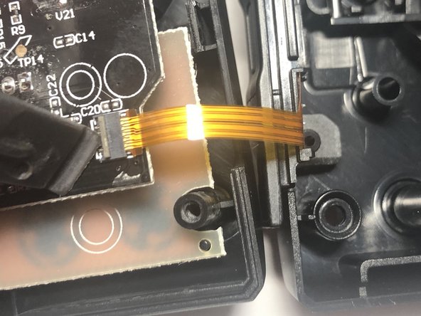
- The ribbon cable is circled in the image.
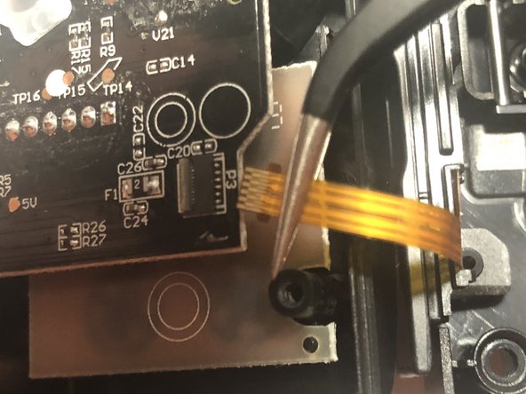
- Use a plastic spudger to flip the ribbon cable latch up as shown in the first two images.
- Remove the ribbon cable from the slot by pulling to the right with tweezers or fingers gently.
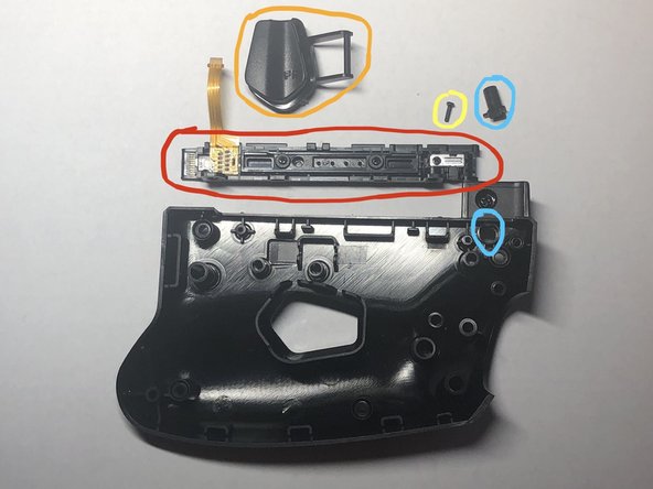
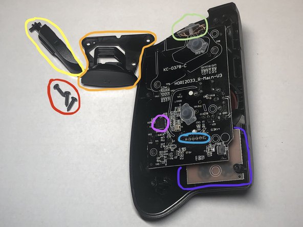
- Remove one PH00 screw that is securing the rail to the back half.
- The FR button can be removed by placing a lever/spudger under the circled area.
- The rail connector can be removed once the yellow circled screw is removed.
- The button that releases the buckle lock can be removed after the rail and goes in the hole circled on the back half of the controller.
- The one remaining screw (not marked) does not need to be removed as it only secures a bit of plastic.
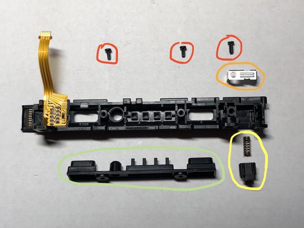
- Remove the three PH00 screws.
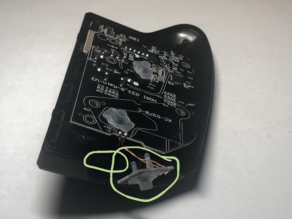
- Pry out the metal cover over the buckle lock. Be gentle so as not to bend the metal.
- The spring loaded buckle lock can then be removed. NOTE: Do not lose the spring when disassembling. Reassembly can be tricky because the spring needs to be compressed to get back in place.
- The plastic cover over the holes in the middle of the rail can be removed. This is where the SL, SR, and connect buttons would be on a normal Joy Con controller and also the lights indicating which controller number it is.
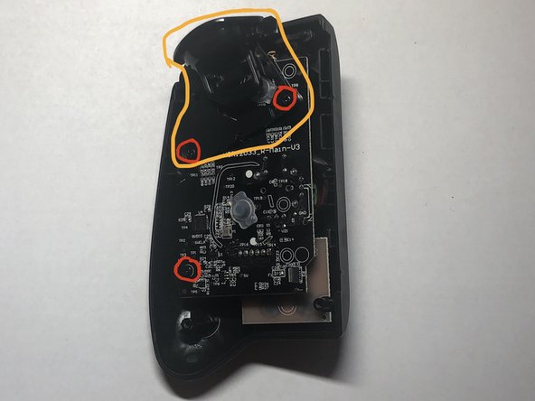
- The ZR button can be removed once the red circled screws are removed.
- The R button is underneath the ZR button and is easily removed once the ZR button is out of the way. There is a small hole that one end of the R button fits into.
- Remove three PH0 screws, two that hold the ZR button plastics and one on the top main board.
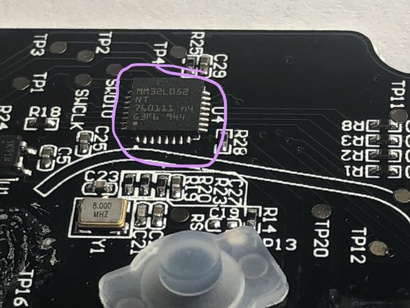
- The processor for the controller can be seen on the top main board. See the details in Step 9??
- The connector between the top and bottom boards is shown here.
- The bottom board on the right controller is small and only picks up the bottom three buttons which using a small 6 pin connector.
- Warning: Do not try to remove the top main board before you remove this small button board in the next step.
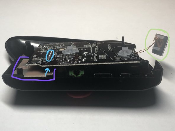
- The small R button board is slid into a slot and has delicate wires that connect it to the top main board.
- Clasp on both sides of the small R button board with your fingers and wiggle it out.
- The top main board is connected to the bottom board with a connector.
- The bottom board is small and underneath the top main board.
- Pull straight up on the top main board and the two boards will disconnect. The connection between them is circled in light-blue. Notice the joystick controller is on the top main board.
- The bottom board is still secured with one screw.
- Remove one PH0 screw.
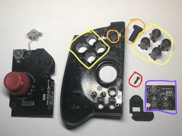
- Remove the plus (+) button.
- Remove the X, A, B, & Y buttons.
- The bottom board can be removed as well as the last rubberized bottom three buttons.
- Notice that this top main board has the same processor as the main motherboard of the left controller. It is MM32L052NT which is a ARM Cortex(TM) M0.