Breville BTA830 Teardown
ID: 132799
Description:
Steps:
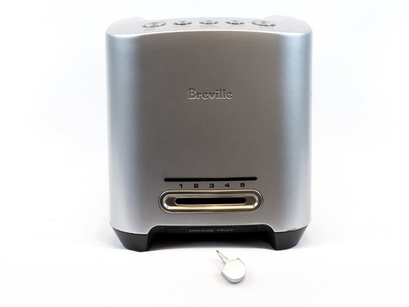
- Before Teardown
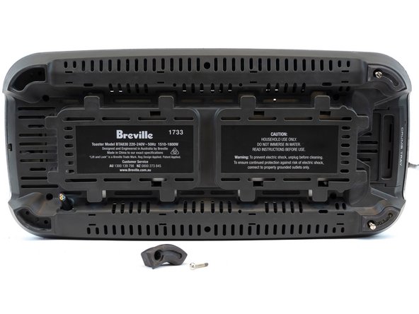
- Turn the toaster upside down
- Unscrew all 6 slotted spanner screws using the slotted spanner head screwdriver
- Then unscrew all 4 slotted Phillips heads screws using a Phillips head screwdriver
- The slotted spanner screws hold 4 rubber feet in place
- Rubber feet can now be detached
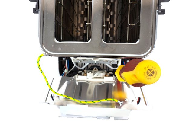
- Detach timer knob using flat head screwdriver, insert screwdriver between knob and sliding hatch and apply slight pressure away from toaster
- Pulling out crumb tray from underneath, using handle
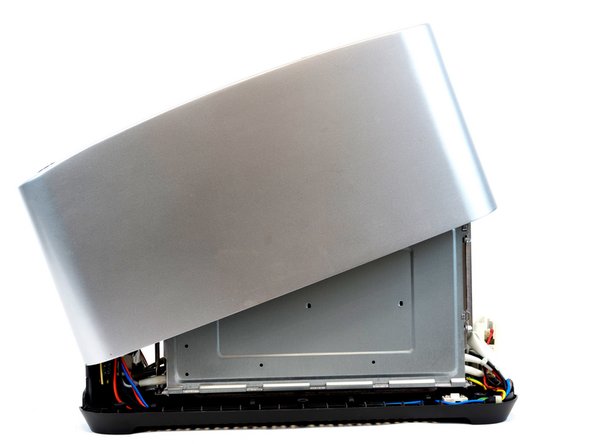
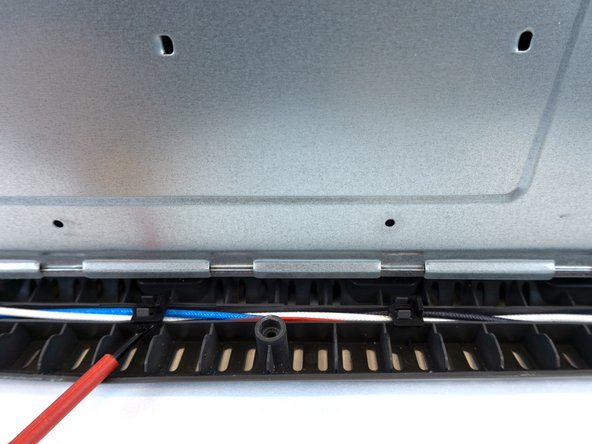
- Lift top casing, being careful of the ribbon cable connected from the casing to the circuit board
- Carefully rest the top casing on the side facing the ribbon cable
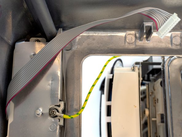
- Disconnect the cable connector by pulling away from the circuit board
- Unscrew the Phillip head screw inside the top casing
- Disconnecting the earth cable from the top casing, and disconnecting the Exterior casing and internal components
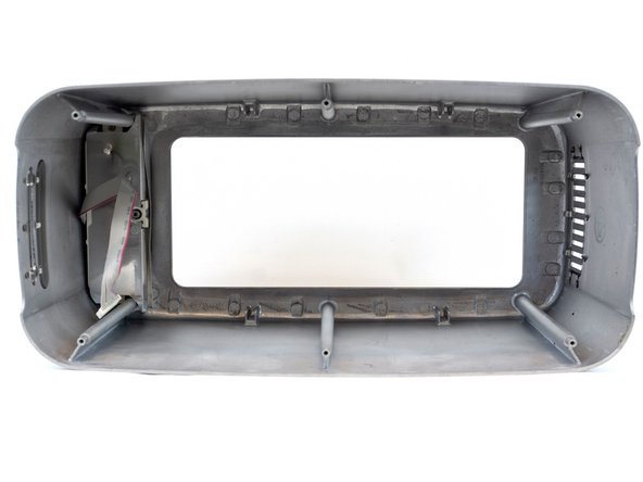
- Place casing on the side, allowing for the removal of the Sliding mechanism frame, LED strip cover and a heat vent grill on the opposite side
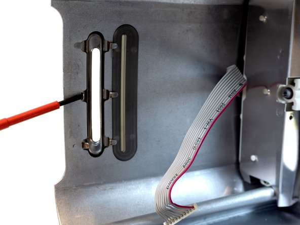
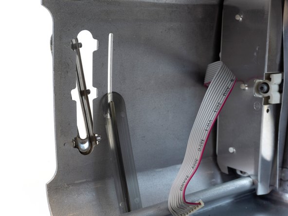
- Detach sliding mechanism frame, by inserting a flat head screwdriver pulling towards the frame, unfolding the 6 metal pieces, releasing the sliding mechanism frame along with the LED strip cover. Which can be pulled out using the flat head screwdriver, with no pressure required
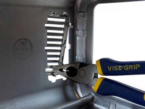
- Using combined pliers, unfold the 10 metal edges holding the heat grill, pushing towards the outer side of the exterior
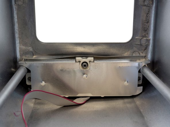
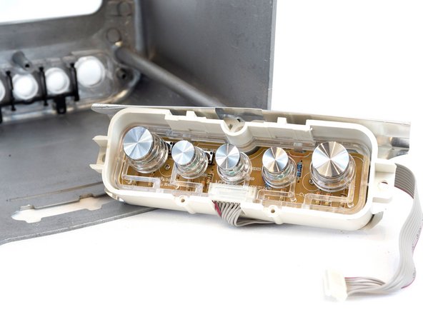
- To access the buttons, remove the 2 Phillip head screws, pulling out the metal plate covering the module, unveiling the buttons
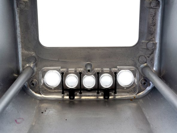
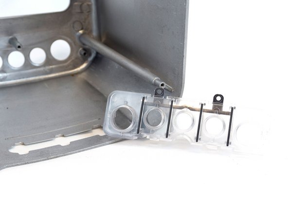
- Clear plastic is easily pulled by hand
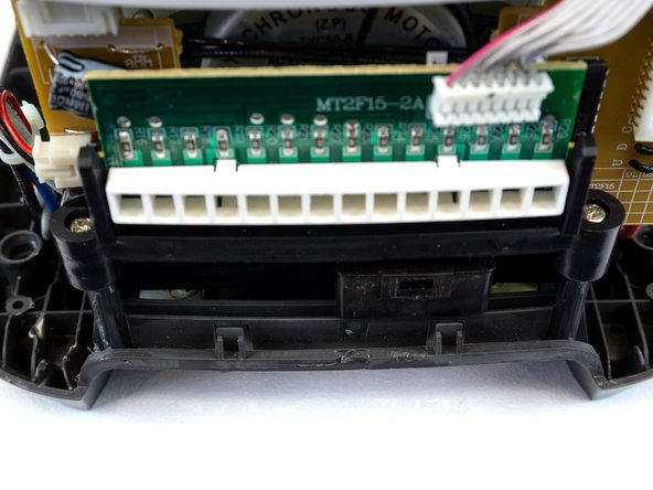
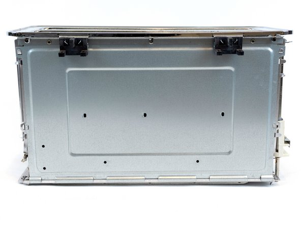
- The interior housing holds 3 circuits boards
- To access the heat controller circuit board, remove the 2 slotted Phillip head screws
- Unclipping the 8-pin ribbon cable
- Allowing for the removal of the heat controller circuit board, the housing along with the sliding mechanism
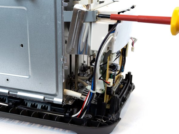
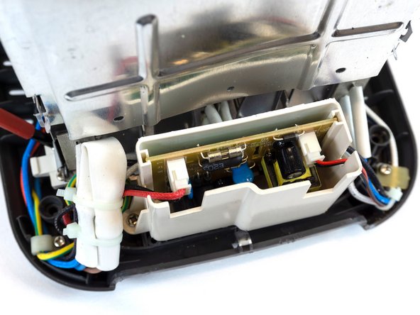
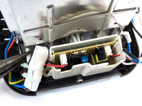
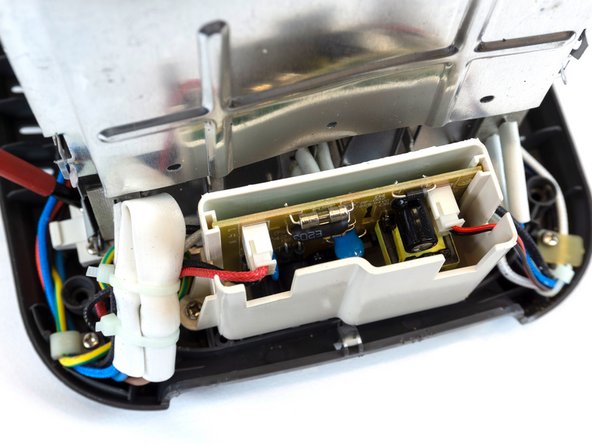
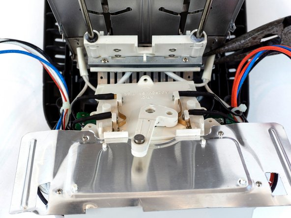
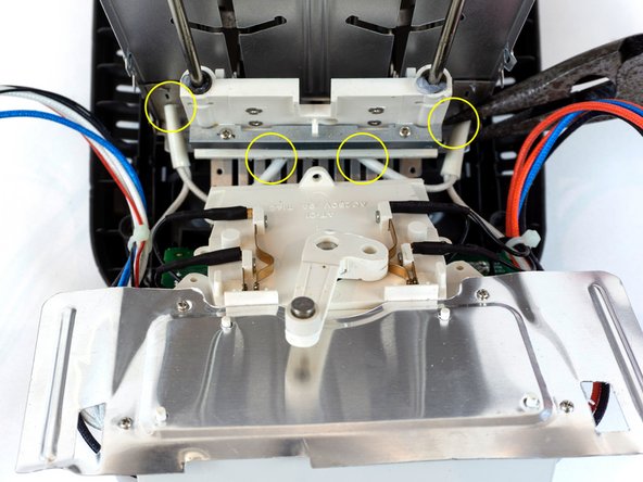
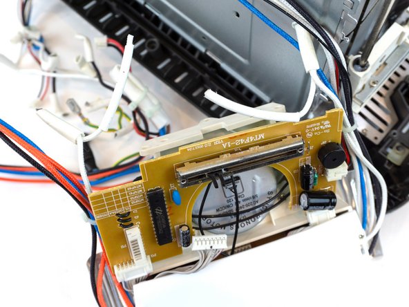
- To access the second circuit board, and shielded electronic components, use a Phillips head screwdriver, to unscrew the two Philips head screws in place, holding the shielded electrical component module
- The shielded module housing will lean back away from the interior components, removing the one Philips head screw, will provide access to the screws on the bottom holding the components
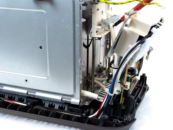
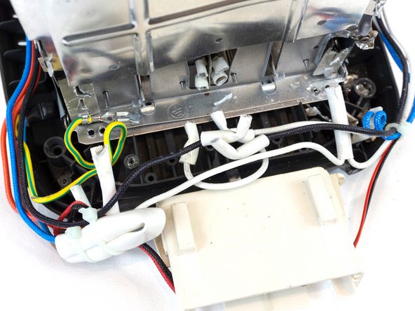
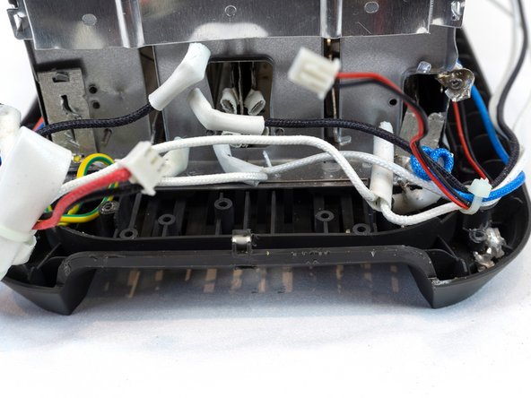
- Removing the 3 Phillip head screws at the bottom holding the housing will disconnect the top wire compartment, with the cables, allowing access to the components underneath
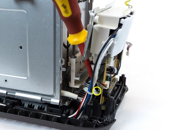
- Pull out earth cable using combination pliers
- Remove cable fasters by inserting a flat head screwdriver into clips, unclipping cables
- Remove the 8 Phillips head screws holding the heating controller compartment from the base
- Cut wires that are inaccessible, connected to the circuit casing
- Pull out / cut any wires still attached to the internal body
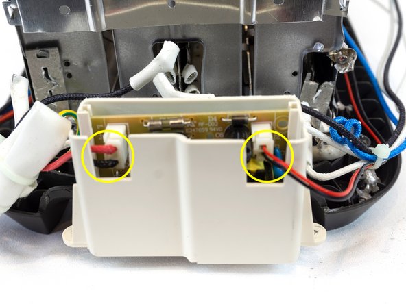
- Disconnect the 2 pin connectors from the circuit board
- Allowing for circuit board module to be removed
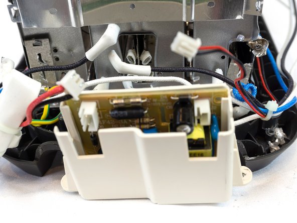
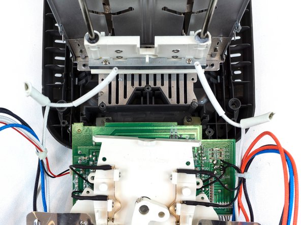
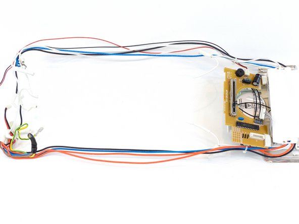
- Cut the wires connecting to the main wire shielded component to the interior body
- Disconnecting the black cables connected to the electrical component
- Disconnect wires connecting to the circuit board on the back of the electrical component
- Electrical Components and Wires are separated from the internal body
- White Wire Housing can be disassembled more by disconnecting / cutting all wires
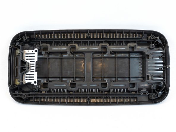
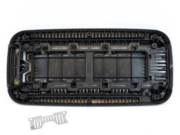
- Unscrew 2 Phillips head screws, separating the metal grill from the base
- Leaving the bottom base by itself
- The internal component to its base, disconnected from the rest
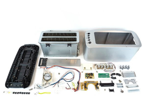
- Final Teardown