Bosch PSR 18 LI-2 - exchange planetary gear with shaft for drill chuck
ID: 132862
Description:
Steps:
- Damage: drill chuck falls off the machine with part of the shaft attached, small bearing rollers fall out of the gear. This indicates a defective planetary gear.
- If the part of the shaft can be removed from the drill chuck (see next step), then a new planetary gear will be required. If it can't be removed a new drill chuck will be required as well.
- Clamp the shaft in a vise
- Open the drill chuck completely by hand
- A PH3 Phillips head screw driver is needed to loosen the screw in the drill chuck by turning it clockwise (left-hand thread!).
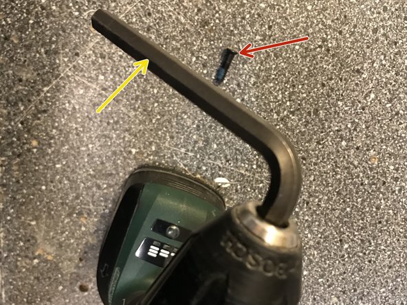
- Clamp an 8 mm Allen key in the drill chuck
- Using an extension, loosen the drill chuck counter-clockwise from the shaft and unscrew.
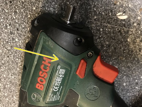
- Lay the device on its left side
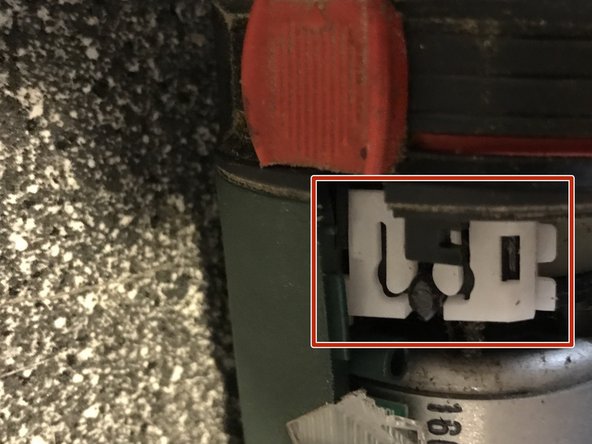
- Set the torque slider to the weakest level (to the left). Still in the middle of the picture
- Unscrew the 9 screws of the right case and the cover with the T10 Torx
- Carefully lift off the case right side.
- Document everything with photos for later assembly :-)
- Remove the right front cover (torque switch still at the lowest level, shown different in the picture).
- Remove planetary gear at an angle to the front and upwards
- If necessary replace left front cover
- After replacing the left front cover (often when removing it), the circuit board and the two-part slider must be reassembled. To do this, thread the black part of the slider into the slots on the circuit board
- Insert the circuit board in the left front cover. The chip is in direct contact with the hole for the fastening screw (the slide control is not shown in the picture).
- Set the slider to the weakest level
- Make sure that the locking element on the black motor mount engages correctly into the slide control catch.
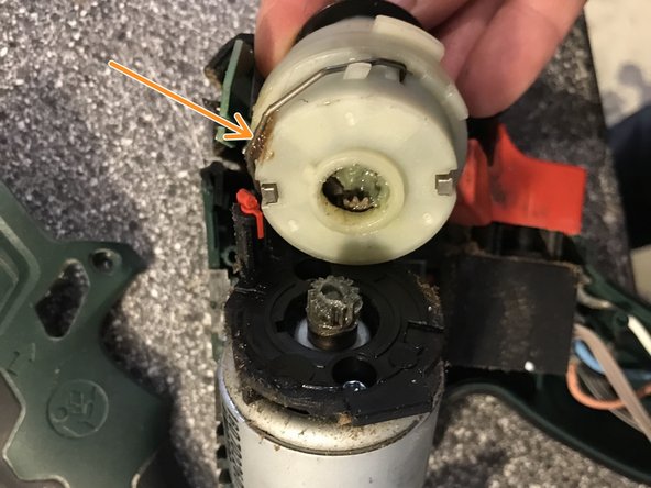
- Insert the white sliding piece (first picture shows it during removal) in the left half of the housing. The 2 lugs fit into the guide shown in the 2nd picture
- Apply grease to the metal bracket on the new transmission
- When reassembling later, the lug on the ring of the gearbox must engage in the groove on the engine mount.
- To install, lift the motor very slightly out of the housing by the drive pinion and place on the gearbox without lifting the circuit board with the slider and sliding piece from the brackets. It may be necessary to turn the gearbox housing slightly axially or slightly tilt it. This step is a bit fiddly.
- Position the motor with the gearbox in the left half of the housing. It will be an easy fit if all the components/cables/... are properly placed.
- Replace the right front cover.
- Replace the right housing shell, at the same time, thread in the two silver end caps. This should go easy and without resistance. If it does not, check the position of the innards again and repeat assembly if necessary.
- Tighten 9 Torx screws.
- Screw the drill chuck onto the thread by hand (clockwise)
- Clamp the 8mm Allen key in the drill chuck and screw the drill chuck on firmly using the Allen key handle.
- Open the drill chuck fully and tighten the screw with a PH3 Philips screw driver in counterclockwise direction (left-hand thread). Use some thread locking compound on that screw.