Karcher Pressure Washer 15209900 2018 Pump Rebuild
ID: 132916
Description: Follow this guide to rebuild the pump for the...
Steps:
- Before you begin, make sure to power off and unplug the device from the outlet.
- Unscrew the output hose from the pressure washer.
- Unlatch and remove the yellow rubber strap.
- Use a T20 driver to remove the two 55mm-long screws securing the hand grip.
- Remove the hand grip from the extension bars.
- Use a T15 driver to remove the six screws securing the top black plastic panels on either side of the device.
- Remove the two plastic panels.
- Remove the two T15 screws securing the plastic feet—one screw on either side.
- Unclip and remove the plastic feet.
- Use a T15 driver to remove the ten screws securing the housing halves together.
- Remove the T15 screw underneath the wheel axle.
- Set the device on its side.
- Lift the housing half away from the body.
- If the housing half does not separate, check to make sure you removed all the body screws.
- Remove the housing.
- Screws may get stuck inside the plastic housing. Be careful not to lose any screws.
- Slide the power cord strain relief out its notch on the plastic housing.
- Lift the motor assembly out of the plastic housing and set it aside.
- Reassembly tip: Use these images to help reassemble the housing back around the motor.
- Make sure that all five bushings are in place.
- In order for the housing to fit properly, the bushings must fit in their respective mounts.
- Make sure that the yellow tube is properly notched onto the housing.
- Make sure that the power cord strain relief sits correctly in the housing notch.
- Use a T20 driver to remove the four screws securing the electrical box cover.
- Lift the cover off of the electrical box.
- Tilt the capacitor upward slightly to gain access to the connectors.
- Use your fingers to pull each capacitor connector directly off of their spade plug.
- Remove the capacitor.
- Reassembly note: The wires are non-polarized and can connect into either plug on the capacitor.
- Remove the plate spring from the electrical box.
- Pull the switch out of the electrical box.
- Disconnect the four spade connectors from the the switch.
- Remove the switch.
- Reassembly tip: Use the second photo as a reference to help you properly re-wire the switch.
- Use a flat head screwdriver to remove the screw securing the ground wire in the electrical box.
- Use a T30 driver to remove the two bolts securing the electrical box to the motor assembly.
- Lift the electrical box away from the motor assembly, taking care to feed the wires through the cutout.
- Remove the electrical box.
- Use a T30 driver to remove the two bolts securing the excess current cover plate.
- Remove the excess current cover plate.
- Use a pair of pliers to grasp the blue tab on the excess current valve.
- Pull firmly to extract the excess current valve from the pump assembly.
- Lubricate the replacement valve's O-rings with the grease included in the rebuild kit.
- Press the replacement valve back into the pump.
- Replace the cover plate with a new one from the rebuild kit.
- Use pliers to grasp the tip of the fine filter in the water intake connector.
- Pull the fine filter out of the intake.
- Replace the fine filter with a new one from the rebuild kit.
- Use a hammer and pin punch to tap the cylinder head plate out of its groove.
- Remove the cylinder head plate.
- Set the motor assembly upright with the pump assembly on the top.
- The pump assembly is filled with oil. This step prevents the oil from spilling out when you remove the pump.
- Use a 13mm socket to remove the four long bolts holding the pump assembly to the motor.
- Re-assembly tip: The bolts hold the pump under pressure against the motor assembly. During reassembly, gradually tighten the bolts in a cross pattern.
- Lift the pump assembly off of the motor.
- Pour the pump oil out of the motor housing. If the oil looks serviceable, save it for reassembly.
- Reassembly tip: The piston assembly is sealed with oil, and the motor housing acts as an oil pan. Before you attach the pump to the motor, fill the piston well with oil, up to the bearing plate.
- Remove the motor/pump O-ring from the motor assembly.
- Replace the O-ring with a new one from the rebuild kit.
- Be sure to lubricate the O-ring with the grease included in the rebuild kit.
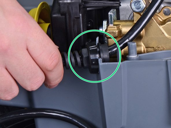
- Use a large flat head screwdriver to loosen the cylinder head from the piston assembly.
- Pull the cylinder head and piston assembly apart.
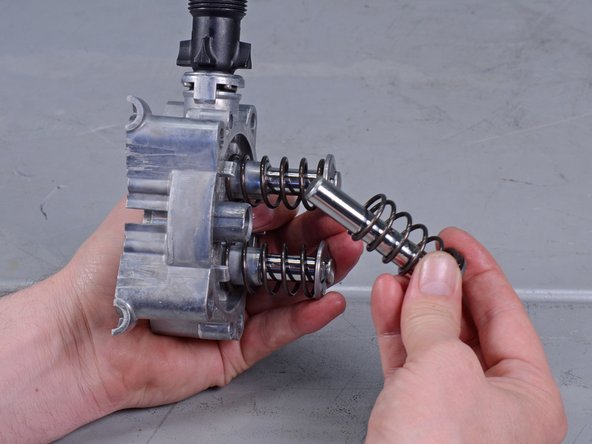
- Remove the three pistons and pressure springs from the piston assembly.
- Return to this step after you have finished the pump rebuild, and follow the instructions in reverse to reassemble your device.
- Reassembly tip: Before putting the pump back together, make sure you have installed the following parts:
- Three grooved rings
- Three suction valves
- One throttle piece
- One joining piece
- Three white washers
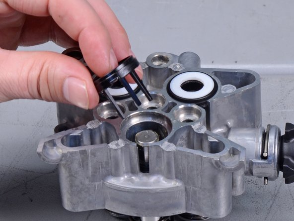
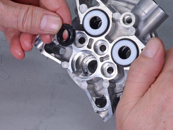
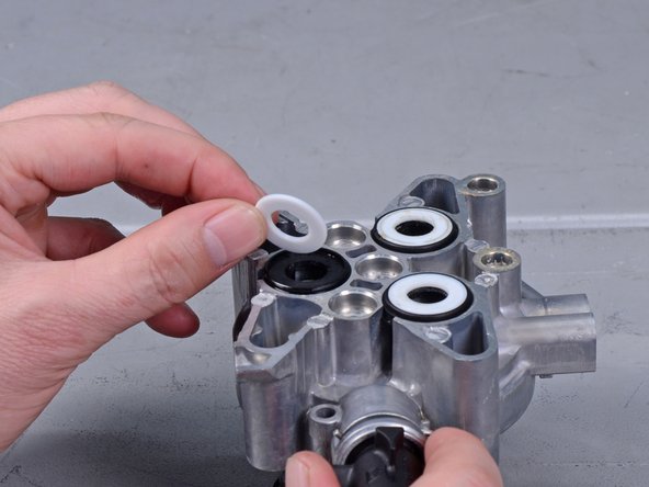
- Use a pick tool to remove the three white washers from the piston cylinders.
- Use a pick tool to remove the three black washers from the piston cylinders.
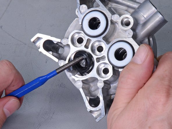
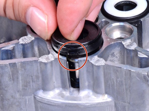
- Use a screwdriver to dislodge and remove the three grooved rings from the piston cylinders.
- Replace the sets of grooved rings, black washers, and white washers with new ones from the rebuild kit.
- Apply grease to the replacement grooved rings.
- Note the orientation of the grooved rings when you insert them into the piston cylinder.
- When you replace the black washers, note that they are keyed to the piston cylinders.
- Use a large flat head screwdriver to unscrew the green nozzle insert from the cylinder head.
- Tip the nozzle down to dump out the nozzle insert.
- Replace the gray valve pin with a new one from the rebuild kit.
- Screw the green nozzle insert back into the port.
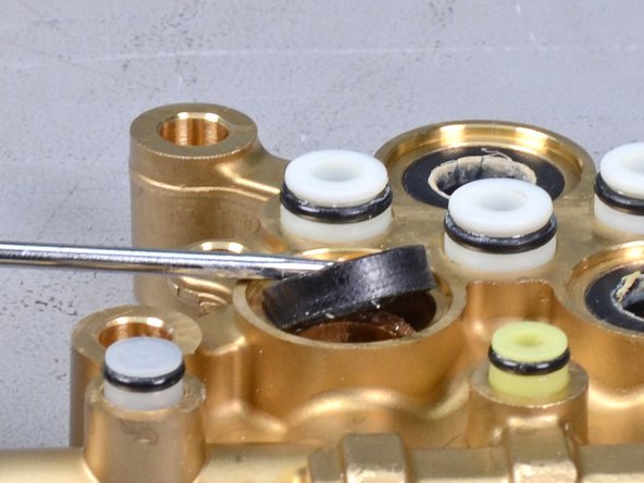
- Remove the three black grooved rings from the cylinder head.
- Replace the rings with new ones from the rebuild kit.
- Reassembly tip: The groove side of the rings should sit against the cylinder head.
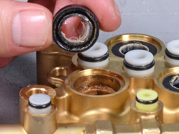
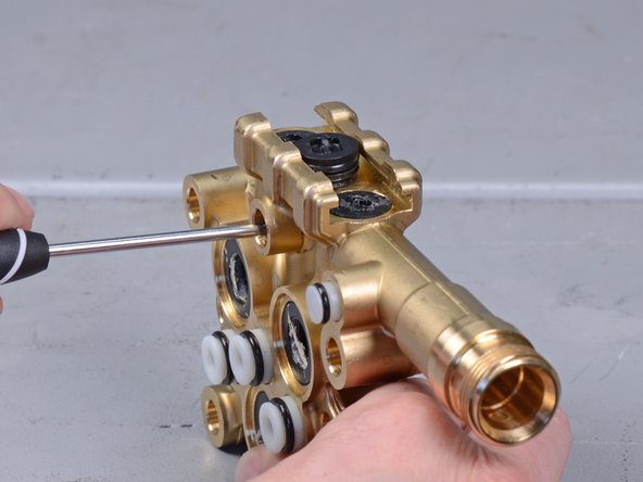
- Use pliers to pull the three suction valves out of the cylinder head.
- Replace the suction vales with ones ones from the rebuild kit.
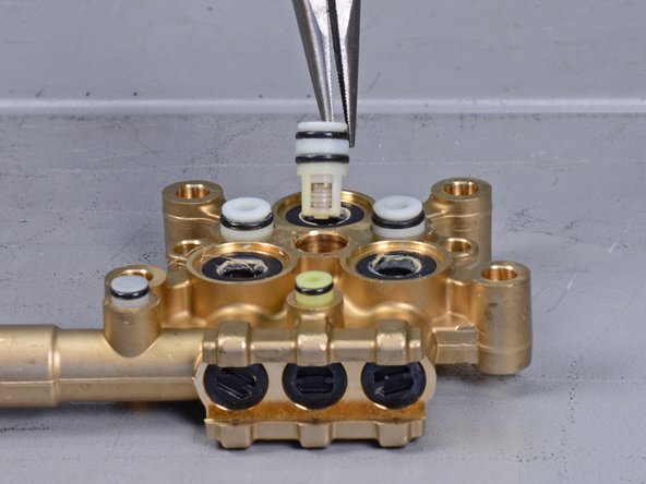
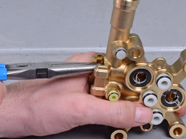
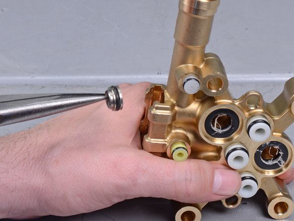
- Use pliers to remove the throttle piece from the cylinder head.
- Replace the throttle piece with a new one from the rebuild kit.
- Reassembly tip: The throttle piece is directional. The end with the larger opening should face the cylinder head.
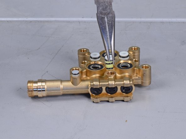
- Use pliers to remove the joining piece from the cylinder head.
- Insert an L-shaped pick tool into the hole that was previously covered by the joining piece.
- Press upwards to loosen the center drain plug.
- The drain plug is firmly held in place and may require significant force to loosen.
- Remove the center drain plug.
- Remove the plastic valve from the center cylinder.
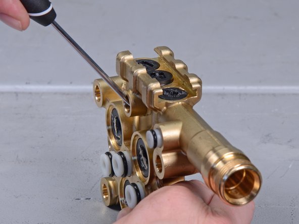
- Insert an L-shaped pick tool into the connecting channel on each side of the center cylinder.
- Press upwards to loosen the drain plug.
- Remove the black drain plug and the plastic valve underneath it.
- Repeat the process for the remaining drain plug and valve.
- It is likely that the metal valve washers did not come out with the plastic valves. Follow this step to remove the metal valve washers from the cylinder head.
- Use needle-nose pliers to grasp the lip on the metal valve washers.
- Pull the metal valve washers straight out of the cylinder head.
- This photo shows how the pieces stack within the cylinder head.
- Replace the drain plugs and valves with new ones from the rebuild kit.
- Drop the valve back into the cylinder head.
- Press the drain plug back onto the cylinder head.
- Replace the joining piece with a new one from the rebuild kit.
- At this point, you should have replaced all the parts that came with your rebuild kit. Click here to jump back to step 38, and follow the instructions in reverse order to reassemble the device.