Karcher Rotary Floor Cleaner 17833080 2017 Gear Case Replacement
ID: 133057
Description: This guide shows how to remove and replace the...
Steps:
- Before you begin, make sure to power off and unplug the device.
- Lift the tank by the handle and remove it from the device.
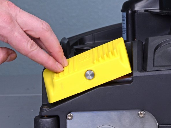
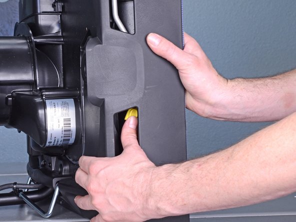
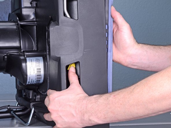
- Press the yellow button near each wheel base to release the wheels.
- Remove both wheels from their sockets.
- Press the yellow foot switch at the base of the device to lower the suction bars.
- Raise the handle to the upright position.
- This will engage the carriage rollers and lift the device.
- Engage the retaining bracket to lock the handle in place.
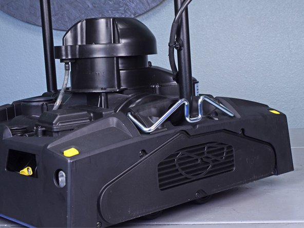
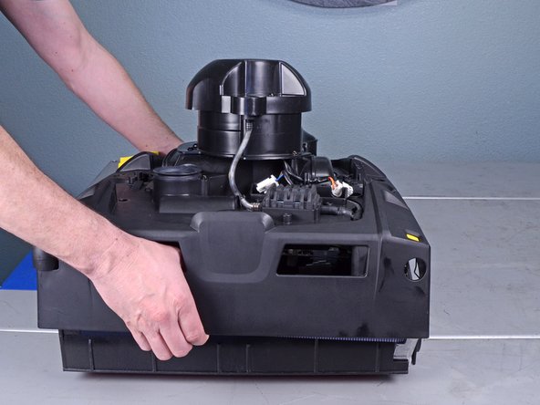
- Grasp the handle and carefully tilt the device onto its side.
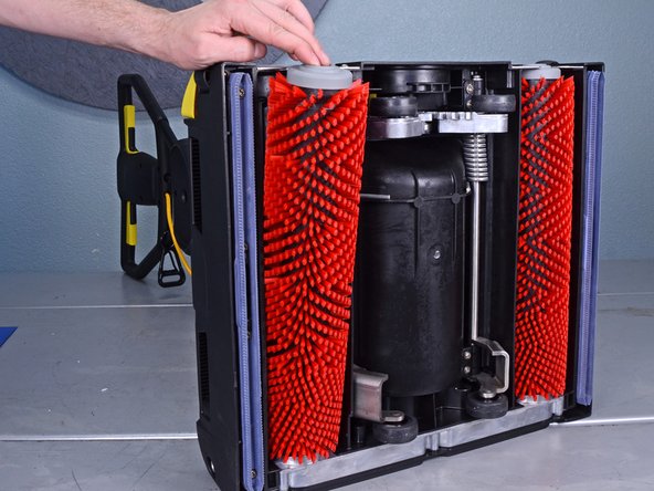
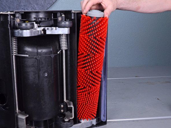
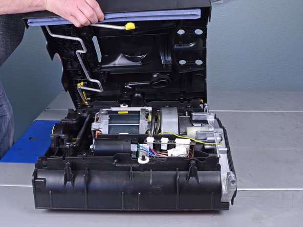
- Tilt the top of the roller brush out of the brush well.
- Remove both roller brushes.
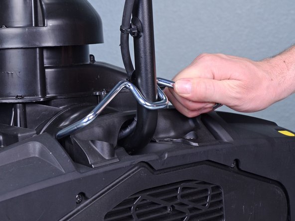
- Press the yellow button on the suction bar retaining bracket to release the suction bar.
- If you can't see the yellow button, press the yellow foot switch at the base of the device to lower the suction bars.
- Remove both suction bars.
- Reassembly tip: When you re-insert the suction bars, be sure to orient the locking tab towards the center of the device. This allows the bars to click in place.
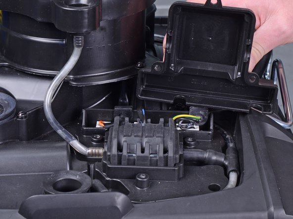
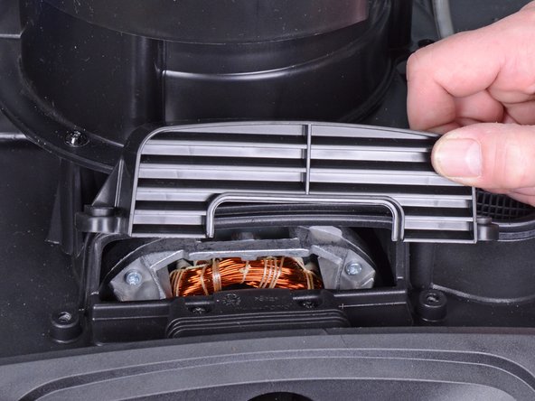
- Use a T20 driver to remove the three screws securing the pump cover.
- Remove the pump cover.
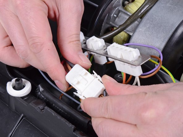
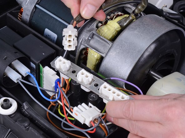
- Squeeze the right plug by the edges and pull it out of its socket.
- During reassembly, make sure that all plugs are firmly seated in their sockets.
- Remove the following screws securing the left retaining bracket:
- Four T40 screws
- Two T20 screws
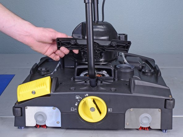
- Raise the handle to the upright position.
- This will engage the carriage rollers and lift the device.
- Engage the retaining bracket to lock the handle in place.
- Use a T20 driver to remove the two screws securing the right splash guard.
- Remove the right splash guard.
- Use a T20 driver to remove the following screws securing the right retaining bracket:
- Two 85 mm-long screws
- Four 45 mm-long screws
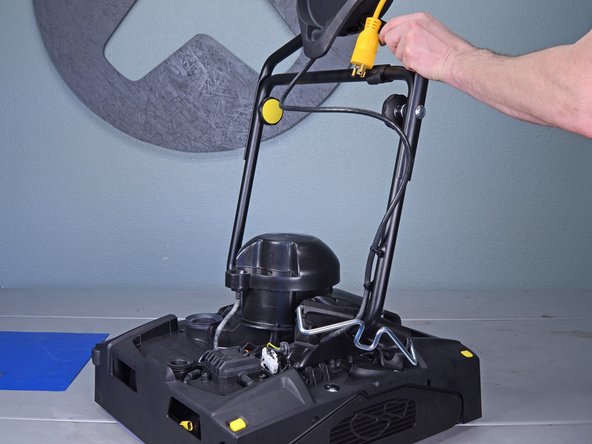
- Remove the right retaining bracket.
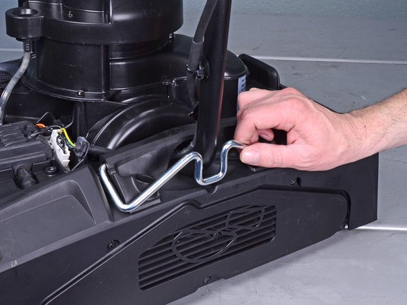
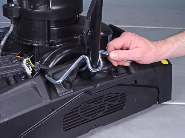
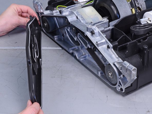
- Lift the handle assembly away from the device and remove it.
- Reassembly tip: Be careful not to lose the two gray bushings on the ends of the handle assembly.
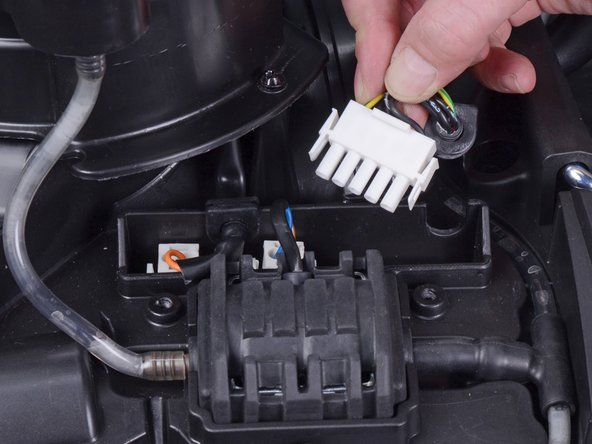
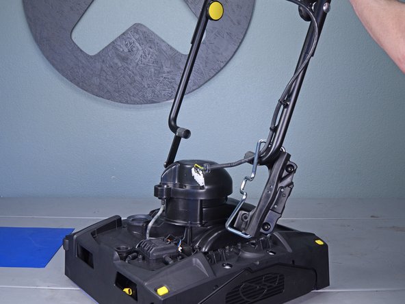
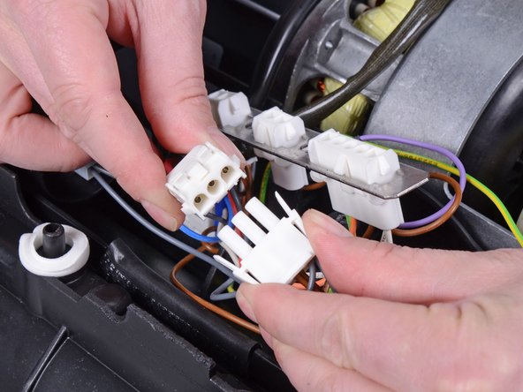
- Disconnect the two remaining plugs by squeezing the edges and pulling them out of their sockets.
- The socket board should have no plugs connected to it.
- Reassembly tip: The sockets reconnect to the following parts:
- Vacuum motor
- Pump
- Handle
- During reassembly, make sure to firmly seat all plugs in their sockets.
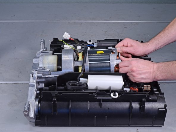
- Use a T20 driver to remove the six screws securing the plastic brush housing.
- Lift the brush housing away from the device and remove it.
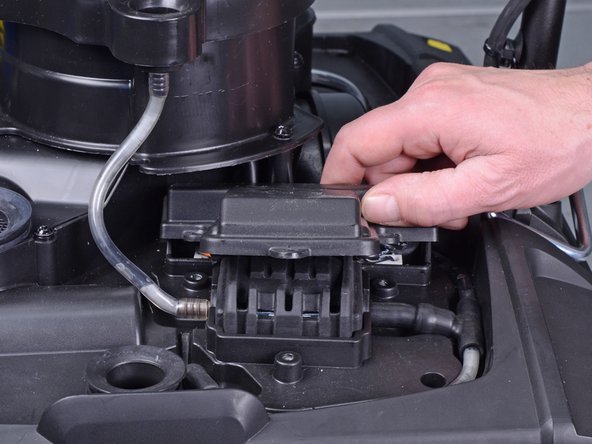
- Use a T20 driver to remove the two screws securing the socket board.
- Squeeze the edges of the drive motor plug and disconnect it from the extension plug.
- The drive motor plug has red, brown, and gray wires feeding into it.
- Free the motor wires from underneath the socket board.
- Reassembly tip: Remember to feed the motor wires back underneath the socket board.
- Use a T20 driver to remove the six bolts securing the gear case cover.
- Remove the gear case cover.
- Remove the following bolts from the gear case:
- Six T20 bolts
- One T30 bolt securing the ground wire
- Reassembly tip: The ground wire's ring terminal should sandwich between a washer and a serrated washer.
- Lift the motor end of the drive assembly up slightly to clear the mounting lip.
- Push the drive assembly out of its recess.
- Reassembly tip: In order for the drive assembly to sit properly in its recess, the motor must clear the mounting lip. If you can't push the motor in far enough, lift it up slightly to clear the lip.
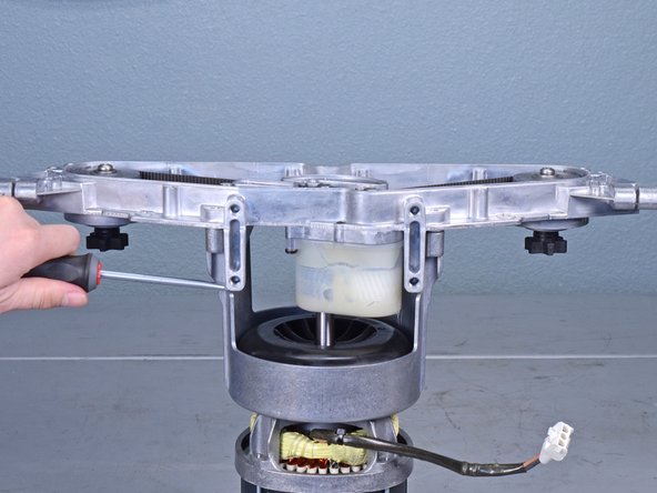
- Remove the drive assembly and stand it on the motor end.
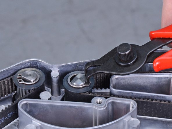
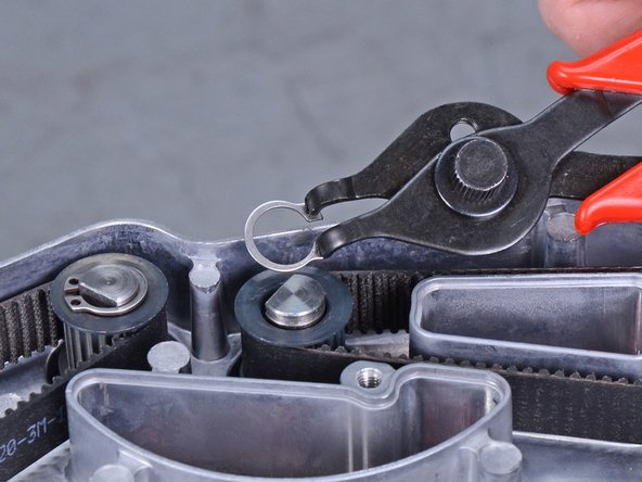
- Use snap ring pliers to remove the retaining ring securing the motor axle.
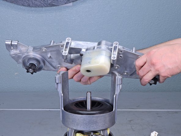
- Use a T30 driver to remove the three bolts securing the gear case to the motor mount.
- Use a pry bar or flathead screwdriver to loosen the gear case from the motor mount.
- Lift the gear case away from the motor mount to remove it.
- During reassembly, follow these tips:
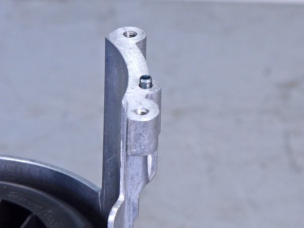
- The motor axle is keyed into the gearbox. Rotate the axle until it aligns with the gearbox slot.
- Align the gear case to the motor mount using the two alignment pins.
- Once everything is aligned, gently tap the gear case onto the motor mount.