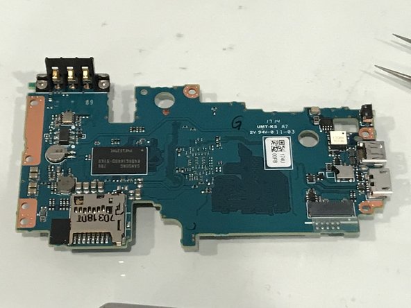
Nikon 1 J5 Main PCB Replacement
ID: 135572
Description:
Steps:
- Remove Micro SD card and Battery
- Remove 2 screws
- Open plastic LCD connector cover
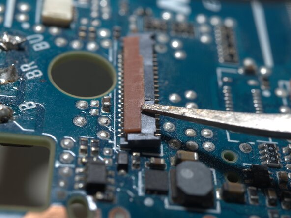
- Lift FPC connector latch
- Detach LCD FPC
- The FPC cable is inserted from right side of this photo.
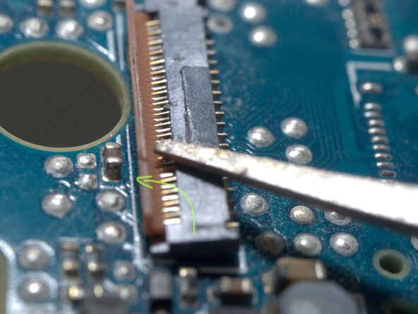
- Insert a fine tip tweezer or any thin flat tip tool under the latch, and gentally lift it.
- The latch rotates CCW for about 90 degrees
- Remove 4 screws
- Remove LCD module
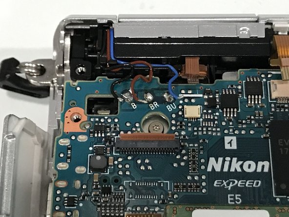
- WARNING!!! DO NOT TOUCH THESE Solder joints!!! High Voltage up to 300V..
- Or discharge the flash condenser first, as per "Main PCB replace guide"
- Remove 3 screws
- Left side, in connector bay, remove 2 screws.
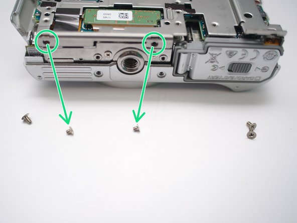
- Bottom, reomve 2 screws
- Right side, remove 1 screw
- Peel here and remove 1 screw within.
- Pop open back case and remove it from body.
- Disconnect speaker
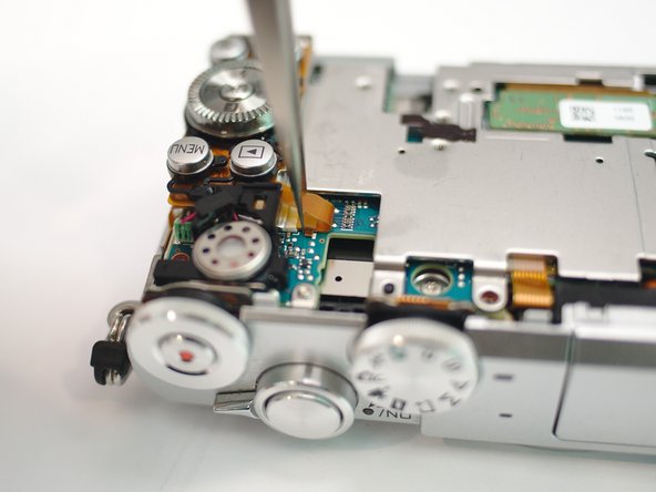
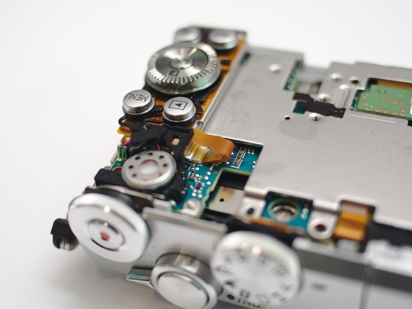
- Disconnect keypad FPC
- Push latches from below
- pop up and remove keypad.
- Caution!!! High DC voltage up to 300V
- Peel tape with an isolated tool (plastic crowbar, plastic tweezers, toothpick etc). DO NOT USE metal tweezers.
- Use a 2-10kohm 5W resistor to discharge flash condenser, for atleast 10 seconds.
- Check voltage across 2 points. Make sure it's below 5V DC
- Remove 3 screws
- Remove 2 screws
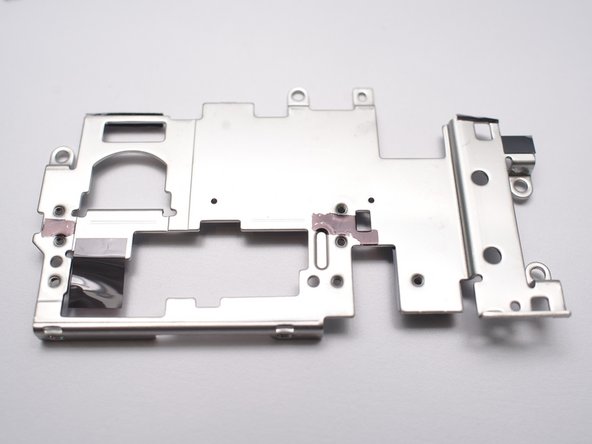
- Remove metal frame.
- Flash solenoid and detect
- Microphones and AF assistant LED
- Keypad
- Switches
- NFC
- WiFi and Bluetooth, Lens(back)
- CMOS sensor
- LCD
- Desolder Flash Condenser
- Desolder flash xenon tube
- Lift top side of main PCB
- Detach (pull out) lens contacts FPC
- Insert wisdom here.