Wacom Cintiq Pro 13 Disassembly
ID: 135590
Description: Wacom Cintiq Pro 13 is a tricky device to disas...
Steps:
- Place the device with the display facing the floor.
- Make sure the surface won't scratch the display of the the tablet
- Remove two rubber feet on both sides of the tablet
- Use plastic tools to lift rubber feet to avoid scratching the back cover
- Remove two #0 Phillips screws hiding under rubber feet
- Remove two T5 Torx screws on the bottom of the device
- Remove two plastic covers as they come loose
- Removing two T5 Torx screws and shields on the top side is not required to disassemble the device
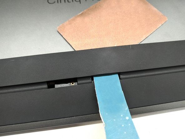
- Heat up the bottom rubber plate near holes using heat gun or hairdryer and try to insert prying tool as adhesive softens.
- A drip or two of isopropyl alcohol on the plastic tools can soften the adhesive even further
- If you're using Heat Gun do not overheat the rubber plate as it may melt. You should be still able to touch the rubber plate with bare hands after heating it up.
- Watch out for ribbon cables hiding in holes, as covers with T5 Torx screws are now removed.
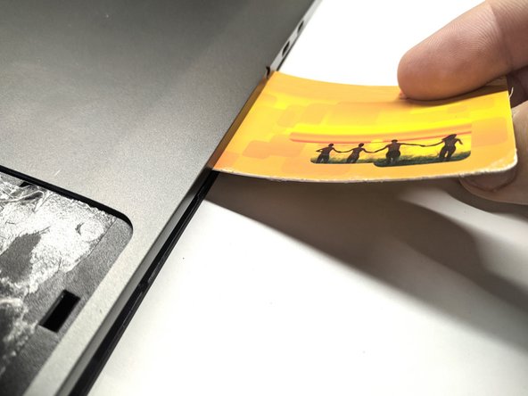
- As the adhesive softens, try to insert flat plastic tool on the top
- Heat up the rest of the rubber plate and slide plastic tool along upper side of the rubber plate
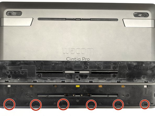
- The bottom side of the plate has plastic clips (third image). Trying to push plastic tool too hard in lower part may result in damaging plastic clips
- Remove the rubber plate
- Remove three #0 Phillips screws
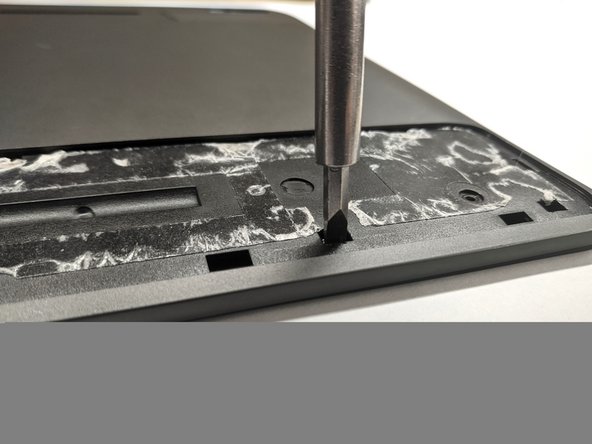
- Unclip ONE of top left/right clips holding back plate to display frame
- Do not push in any of red circled holes - it may break ribbon cables, display or front glass
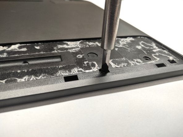
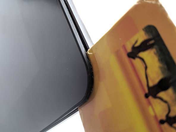
- Push gently on the clip to allow flat plastic tool to be inserted on the corner of the device
- Pushing too hard or pushing in holes circled red in last step may result in damage
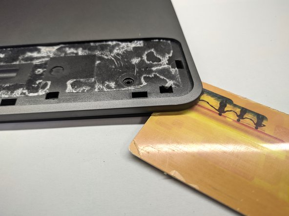
- Insert flat plastic tool between the rubber glass frame and the back panel
- Unclip rest of visible clips
- The bottom part of the device will come loose allowing you to place finger between the case and the display assembly
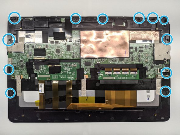
- Unclip hidden clips on left or right side and continue to opposite side. Plastic flat tool may come in handy here
- You can insert plastic tools up to 2 cm / 1 inch inside and not damage anything. Third image will guide you through clips and other obstacles
- Unclip all twelve clips. Keep one hand on the display to decrease display bending and second to slowly lift the back cover.
- There is nothing connected to the back panel - no need to worry about hidden flex/ribbon cables
- Remove the back cover
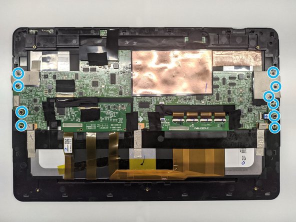
- Remove ten #0 Phillips screws
- Remove the shielding and various tape strips holding cables
- Pulling too fast and/or too hard may disconnect cables with the shielding or tape strips causing them to be damaged or even damage cable connectors on the mainboard
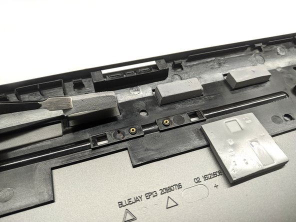
- Remove thermal pads
- You can place thermal pads onto the back plate, as there are special holes for every of them
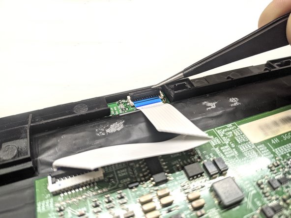
- Release the latch of the audio jack flex cable port on the mainboard
- Try to slide the flex cable towards the audio jack board and then lift it up
- Release the latch of the control board flex cable
- Try to slide the flex cable towards the mainboard and then lift it up
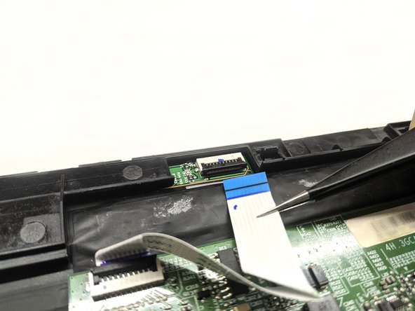
- Repeat the procedure for the flex cable connector on the mainboard
- Remove the cable
- Remove the digitizer board cable
- Try to hold it as near the plastic connector as possible and then pull it towards the digitizer board
- Do not pull by the middle or opposite end of the cable
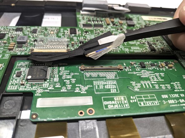
- Remove the adhesive from the mainboard
- Do not remove it entirely - it's a part of the cable
- Slide the cable towards the mainboard by holding it as near the connector as possible
- Do not pull by the middle or other end of the cable
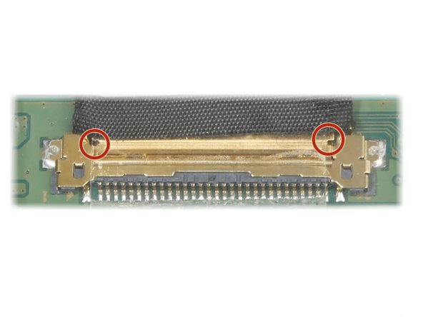
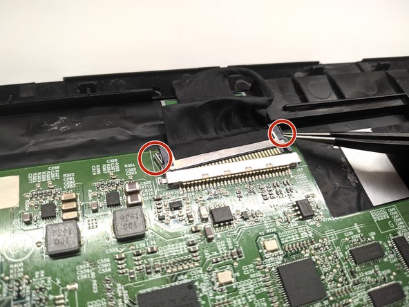
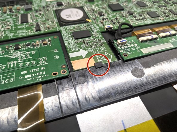
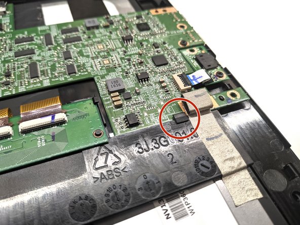
- If cable seems hard to remove, try to push one side of the connector using a pair of tweezers by spots marked on third image
- Do not push center part of the connector as it can be easily bent
- Repeat the steps for another end of the cable connected to the mainboard
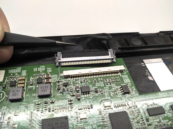
- Remove the display connector
- Press on the latch on left or right side of the cable
- Slide one part of the cable just a bit
- Repeat steps for the other side of the cable
- Slide out the cable
- If you wish to replace the cable, steps to disconnect the cable from the LCD display are the same as digitizer cable from last step
- Do not pull by the cable - try holding onto the plug
- Remove the mainboard by sliding it forward and then lift it up
- Watch out for three clips holding the mainboard on the bottom side of the tablet