Dell DJ 2nd Generation Disassembly
ID: 135830
Description: Repairing the DJ may seem like a daunting task....
Steps:
- The lock switch slider can be removed with a small prying tool. Make sure it doesn't go flying across the room!
- The cover is affixed with adhesive. It can be pried off.
- Don't start with an opening pick. Instead, use an iFixit Opening Tool and start around the charging port.
- When it's lifted up far enough, wedge an opening pick between the case and the cover.
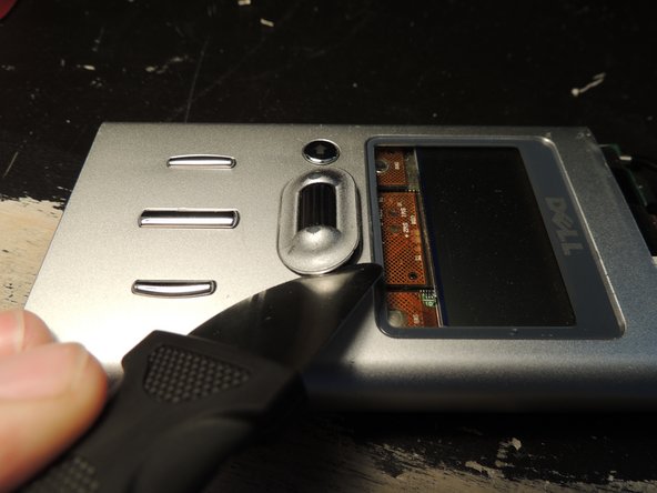
- If necessary, you can use the Jimmy to pry around the edges. Be gentle, as it's very easy to damage the aluminum case.
- The top cover put up more of a fight. I had to use the Jimmy for this one.
- Again, use caution to avoid damaging the case. It's also important to avoid bending the top cover sharply.
- There are eight Philips #00 screws, one on each corner at both ends of the device.
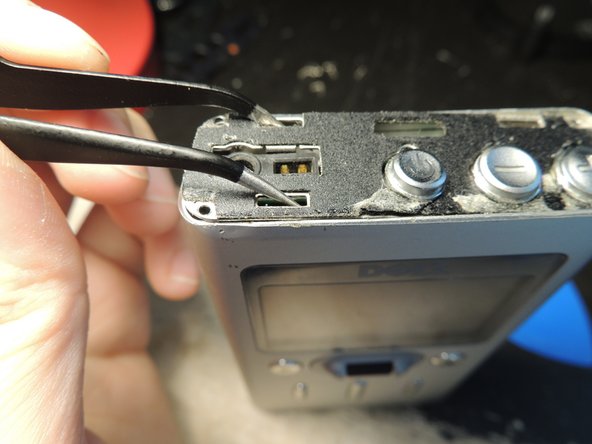
- I don't recommend using tweezers to remove the plates like I did. You might bend the tips.
- Be careful to avoid bending the battery. It is very thin and prone to damage.
- Disconnect the battery connector. Then, gently pull the wires until the battery slides out.
- If the battery doesn't slide out, use a blunt but thin tool (such as the flat end of an iFixit Spudger) to push the battery from the other end.
- Try something other than a Jimmy first. It can damage both the encoder's housing and the aluminum case.
- It may help to push the internals towards the top slightly, but they won't come out yet.
- The internals should come out easily. If it seems to catch on something, wiggle it around gently.
- Be careful not to scratch the display.
- Lift up the tabs on both sides.
- Lift the left side of the display completely.
- Don't force the tabs on the right; just unlatch them and push them up slightly so they don't snap back into place.
- Use your soldering iron to melt the solder holding the metal frame to the board. Use a small tool to gently pry the display up.
- Push the ends of the brown latch towards the screen, then remove the display.
- There are four Philips #00 screws holding the hard drive in. They're the same as the eight screws you removed earlier, so don't worry about mixing them up.
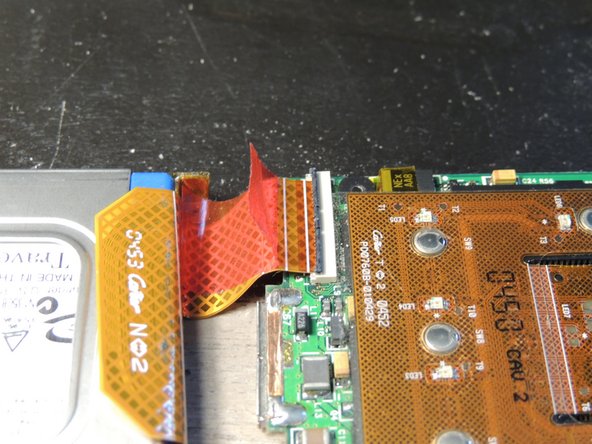
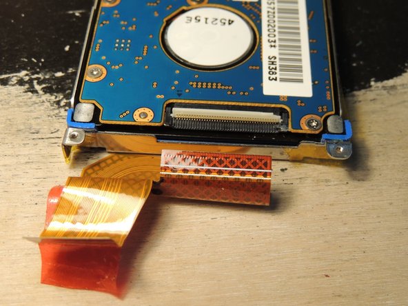
- Peel back the red tape. Then, lift up the latch and pull the cable out.
- This connector is the same as the one on the mainboard. The latch is beige on this one.
- Gently push on the label side of the hard drive to remove it from the frame.
- Push the brown latch towards the keypad, then pull the cable out.
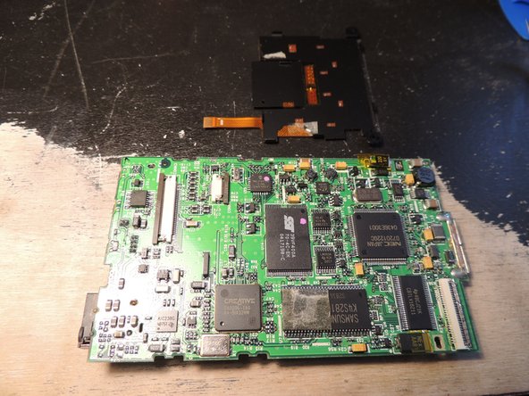
- The keypad is only held on by a bit of double-sided tape on the RAM chip.