Technics EAH-AZ70 (Japan) Bluetooth Headphones Teardown
ID: 135886
Description: A look inside the Technics EAH-AZ70 (Japan) /...
Steps:
- Features:
- Highest Level of Dual Hybrid Noise Cancelling. Multiple MEMS microphones
- Graphene coated PEEK diaphragm speaker for smooth, clean, and elegant sound
- Stable Connection in crowed areas
- Excellent Quality Call Sound
- Approximately 6.5 hours of playback, and up to 20 Hours of use with charger
- Bluetooth® 5.0
- Capacitive touch sensor control
- What is in the box
- Headphones / Charging Case
- USB 'C' Cable
- Headphone rubber tips for different sizes of ears
- User's Manual
- Charging case with headphones
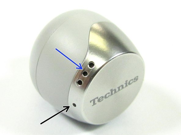
- Close up view of headphones
- Side views of Headphone
- Charger Interface
- USB Interface
- Speaker Sound Port
- MEMS Microphones
- Speaker Vent
- Vent Port
- Speaker Spatial Vent Port
- View of Headphone with rubber ear piece removed
- Vent Port
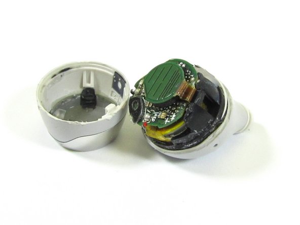
- Since the Technics Headphone enclosure is glued together, the only way in was to cut into the headphone.
- This is a destructive teardown
- A Razsor knife was use to cut into the Technics headphone along the seam in the headphone. Then a Jimmy Tool was used to open up the headphone. Tweezers and a Pick Tool were used to removed the electronics from the enclosure
- Once opened, we get our first look at the inside of the headphone
- Double sided foam tape was used to hold the main the PCB to the Battery and to the Touch Sensor / Antenna PCB. This foam tape had to be cut free. Then Denatured Alcohol was used to remove the foam tape glue from the PCBs and Battery
- Double Sided Foam Tape
- Opening up the headphone, we can see the main PCB, Battery, Speaker, etc
- Battery
- Main PCB
- Speaker
- Speaker Sound Chamber
- Touch Sensor and Antenna
- At first, I wasn't sure about the solder balls. Then I realized they were used to anchor the USB and Power Interface pins on the outside of the Headphone to the internal circuit board.
- I had to used a solder iron to remove the solder balls, so that the internal interface circuit board could be removed. I had to also remove solder from the speaker wires to free up the internal circuit board.
- Internal Circuit Board that interface Power and USB to the Headphones
- The internal circuit board was also attached a MEMS Microphone that appeared to be monitoring the Speaker Chamber of the Headphone, since it was faced in
- I had to remove the outside panel with 'R' on it with a Razor Knife to free the MEMS Microphone. Once the MEMS Microphone was freed, the interface board circuit could be pulled out
- USB and Power (Charger) Interface
- Sound Ports
- Internal Circuit Board that interface Power and USB to the Headphones
- MEMS Microphone from plastic collar in the Headphone
- MEMS Microphone separated from the Interface Circuit Board when removed from the side of the Speaker Chamber
- There was not much to see on the internal interface board top side or bottom side. The was one IC component that could not be crossed. If you happen to know the component, please leave a comment below
- Unknown Component
- Full Sensor Flex/Charging PCB IC Identification:
- You may need to enlarge the picture to view the text.
- Next the Speaker sound chamber cover was removed with the use of a Pick Tool and Tweezers. A Razor Knife was used to cut the glue holding the speak in place
- The speaker had no identifiable markings
- With Speaker removed, we can see the sound chamber and sound ports
- Closeup view of the Battery
- Li-Ion 3.7V, 0.32Wh
- The battery appears to be from VDL Electronics Co., Shenzhen, China
- Closeup view of the Antenna/Touch Sensor side of the Main PCB
- DSP Group - C2A1A Hybrid Active Noise Cancellation (ANC) Codec and Audio Digital Signal Processor (DSP)
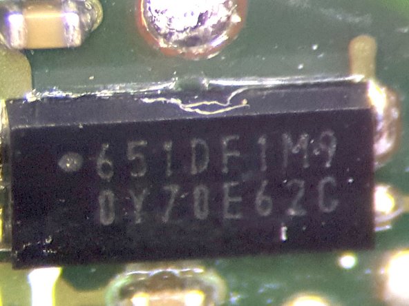
- 651DF1M9 - Could not cross part number, but during a web search found out that it may be an integrated battery management IC
- W25Q32JWUUIMTR- SPI FLASH 32Mb
- MEMS Microphone Port
- Closeup view of some of the components on the Antenna/Touch Sensor side of the Main PCB
- DSP Group - C2A1A Hybrid Active Noise Cancellation (ANC) Codec and Audio Digital Signal Processor (DSP)
- Winbond-W25Q32JWUUIMTR SPI FLASH 32Mb
- 651DF1M9 - Could not cross part number, but during a web search found out that it may be an integrated battery management IC
- Battery side close up view of the Main PCB
- AIROHA AB1552 - ARM Cortex M4/Bluetooth 5.0 Dual Mode
- 913 MPS1 MEMS Microphone. The Headphone uses three MEMS microphones with this part number
- Could not cross the part number. If you know the part, please leave a comment below. The 2D bar code on the part reads as STM9135G15JAS011
- Crystal Oscillator
- Unknown component. Labelled B2A. Please leave a comment if you happen to know this component
- Unknown component. Labelled SV4CP 240. Please leave a comment if you happen to know this component. Separated from PCB during teardown
- Closeup view of some of the components on the Battery side of the Main PCB
- AIROHA AB1552 - ARM Cortex M4/Bluetooth 5.0 Dual Mode
- 913 MPS1 MEMS Microphone. The Headphone uses three MEMS microphones with this part number
- Could not cross the part number. If you know the part, please leave a comment below. The 2D bar code on the part reads as STM9135G15JAS011
- Unknown component. Labelled SV4CP 240. Please leave a comment if you happen to know this component. Separated from PCB during teardown
- Closeup view of top and bottom side of the Touch Sensor Flex PCB and Antenna
- Full Main PCB IC Identification:
- You may need to enlarge the picture to view the text.
- Predicted Block Diagram of the Technics EAH-AZ70 (Japan) Bluetooth Headphones:
- You may need to enlarge the picture to view the text.
- Teardown Exploded View of the Technics Headphone