MacBook Air 13" Early 2017 Heat Sink Replacement
ID: 135932
Description: Use this guide to replace the heat sink, or...
Steps:
- Before proceeding, power down your MacBook. Close the display and lay it on a soft surface, top-side down.
- Use a P5 Pentalobe driver to remove ten screws securing the lower case, of the following lengths:
- Two 9 mm screws
- Eight 2.6 mm screws
- Wedge your fingers between the display and the lower case and pull upward to pop the lower case off the Air.
- Remove the lower case and set it aside.
- To ensure that everything is de-energized and won't turn on while you're working, it is recommended that you disconnect the battery.
- Grab the clear plastic pull tab attached to the battery connector and pull it parallel to the board toward the front edge of the Air.
- Do not lift upward on the connector as you disconnect it or you risk damage to the connector socket.
- Use the flat end of a spudger to pry the I/O board cable connector up out of its socket on the I/O board.
- Carefully peel the I/O board cable from the adhesive securing it to the top of the fan.
- During reassembly, make sure this cable is in the correct orientation. It will fit if reversed, but the laptop will not boot.
- The following connector has an especially deep socket. Use care when disconnecting it.
- While gently pulling the I/O board cable upward near its connection to the logic board, use the flat end of a spudger to pry up on alternating sides of the connector to help "walk" it out of its socket.
- Remove the I/O board cable.
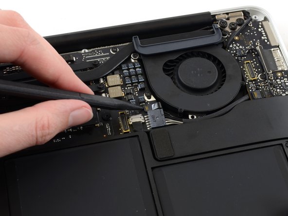
- Use the tip of a spudger to carefully flip up the retaining flap on the fan cable ZIF socket.
- Be sure you are prying up on the hinged retaining flap, not the socket itself.
- Peel the rubber gasket off the adhesive on the top of the fan.
- Remove the following three screws securing the fan to the upper case:
- One 5.2 mm T5 Torx screw
- One 3.3 mm T5 Torx screw
- One 4.4 mm T5 Torx screw with a short head
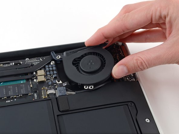
- Lift the fan from the I/O board side and pull it free from the upper case.
- Removing the fan will also disconnect the fan ribbon cable. Be careful not to snag it.
- Disconnect the I/O board by pulling its power cable away from its socket on the logic board.
- Pull the cable parallel to the face of the logic board toward the right edge of the Air.
- Use the flat end of a spudger to pry the left speaker cable connector up and out of its socket on the I/O board.
- Pry up from beneath the wires.
- Use the tip of a spudger to carefully flip up the retaining flap on the microphone ribbon cable ZIF socket.
- Make sure you are flipping up the retaining flap, not the socket itself.
- Remove the single 4.1 mm T5 Torx screw securing the I/O board to the upper case.
- Gently de-route the camera cable from its notch on the I/O board and push it out of the way with the tip of a spudger.
- Lift the I/O board from the logic board side and pull it free from the upper case.
- Removing the I/O board will also disconnect the microphone ribbon cable. Be careful not to snag it.
- Remove the two 4.9 mm T8 Torx screws securing the antenna cable retainer on the left display hinge to the upper case.
- Push the antenna cable retainer out of the way and remove the single 3 mm T5 Torx screw securing the end of the heat sink to the upper case.
- Remove the four 2.5 mm T5 Torx screws securing the heat sink to the logic board.
- If the heat sink seems to be stuck to the logic board after removing all five screws, use a spudger to carefully separate the heat sink from the faces of the CPU and GPU.
- Remove the heat sink from the logic board.
- When reinstalling the heat sink, be sure to apply a new layer of thermal paste. If you have never applied thermal paste before, we have a guide that makes it easy.
- When reassembling your device, attach the gasket to the heat sink as shown.
- The tail of the gasket should fit into the notch in the heat sink, it should not end up underneath the heat sink tab that will rest on the logic board.
- Be sure the small post molded into the rubber gasket mates with the hole cut into the upper right corner of the logic board.
- If you're replacing the heat sink, you can reuse the existing gasket.