Honda 3000 Watt Inverter Generator EU3000IS1AWK Control Wire Harness Replacement
ID: 136206
Description: This guide shows how to remove and replace the...
Steps:
- Before you begin, make sure the generator is off and cool to the touch.
- Use a large flathead screwdriver to unlock the maintenance cover.
- Open the maintenance cover.
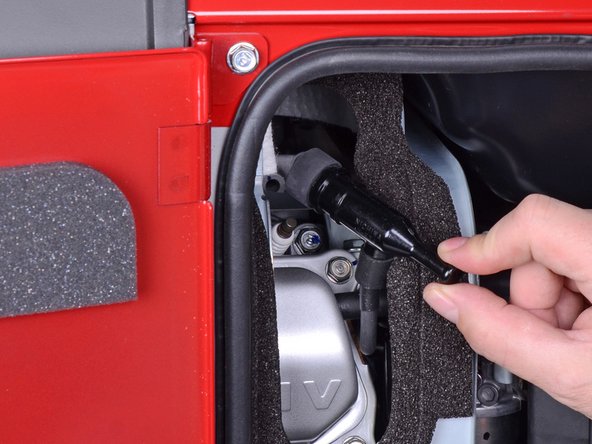
- Use a Phillips screwdriver to remove the screw securing the spark plug cover.
- Remove the spark plug cover.
- Grab the plastic housing at the end of the spark plug wire.
- Pull firmly to disconnect the wire from the spark plug.
- Turn the fuel valve to the cutoff position.
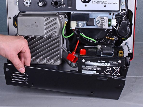
- Use a 10 mm socket to remove the four capped nuts securing the front cover.
- Remove the front cover.
- Use an 8 mm socket to disconnect the battery wires from the battery terminals.
- Disconnect the black negative cable first to prevent the risk of shorting the battery.
- During reassembly, connect the black negative cable first. Make sure you reconnect the wires in the correct polarity.
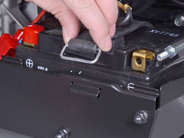
- Unclip the battery strap from the lower plate.
- Remove the battery.
- Use a 10 mm socket to remove the four capped nuts securing the lower plate.
- Set these capped nuts apart. They look similar, but are smaller than the front cover nuts.
- Remove the lower plate.
- Insert a flathead screwdriver into the top of the brown fuse clip in order to release the fuse holder.
- Detach the fuse holder from the brown clip.
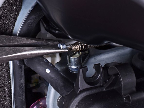
- Use pliers to lift and disconnect the choke cable from the choke stay.
- During reassembly, be sure to test the choke to ensure that it is properly connected.
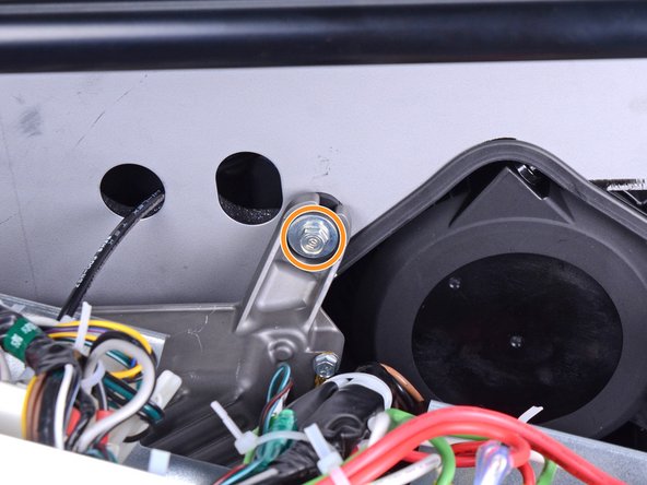
- Use a long shaft Phillips screwdriver to remove the deeply recessed screw securing the fuel cutoff switch.
- Be careful not to turn the fuel cutoff switch while you remove the screw.
- Remove the fuel cutoff switch.
- During reassembly, be sure to test the switch to ensure that it is properly installed.
- Use a 10 mm socket to remove the four bolts securing the control panel.
- Carefully tilt the control panel downwards.
- The control panel will still be connected to many wires and cables. Be careful not to strain any of the connected wires.
- Remove the following bolts securing the inverter:
- One 8 mm ground bolt
- Three 10 mm bolts (one behind the control panel)
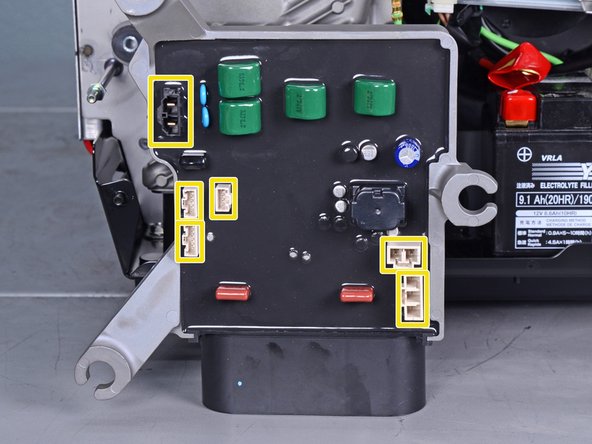
- Reach behind the inverter along the edges and disconnect the six connectors from the back of the inverter.
- All the connectors use locking tabs, so you will have to squeeze them in order to release them.
- The third image shows the locations of all six sockets on the inverter.
- Reassembly tip: Every socket on the inverter is different, so you can't plug something into the wrong place. Do not force the connectors into their sockets.
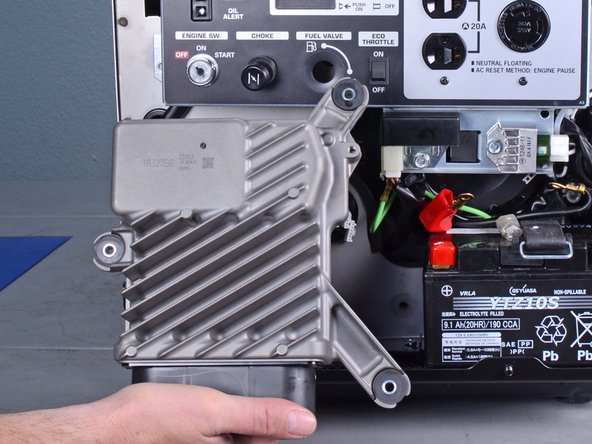
- Remove the inverter.
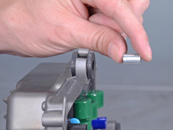
- If you are replacing the inverter and the replacement did not come with rubber mounts, follow the next two steps to transfer them over.
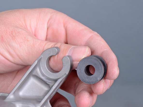
- Use a screwdriver to push the metal collar out of the center of the rubber mount.
- Squeeze the mount and remove it from the inverter.
- Repeat the procedure with the remaining mounts and transfer them to the replacement inverter.
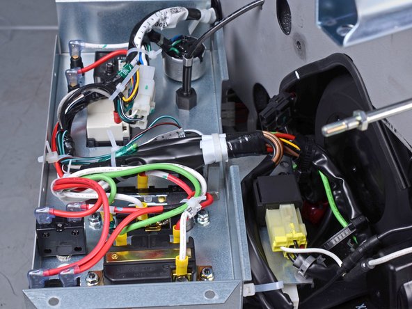
- The remaining steps show all the connectors you need to disconnect in order to replace the wire harness.
- To help keep track of the connectors, disconnect each one from the old harness and immediately connect it to the new harness.
- Most connectors are keyed to plug in one orientation. Do not force the connectors.
- Be sure to replace any cable ties you removed along the way.
- During reassembly, use these images as reference for how the harness is secured to the control panel.
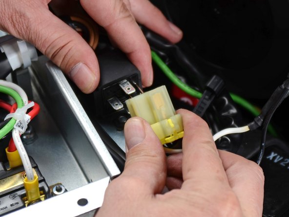
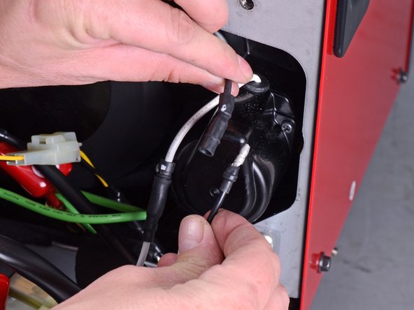
- Unplug the five-wire starter relay connector.
- Unplug the starter motor's black and white barrel connectors.
- The wires should be connected to their respective colors.
- Unplug the two-wire oil switch connector.
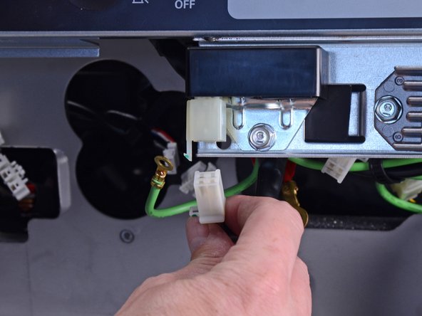
- Unplug the four-wire rectifier connector from the bottom right corner of the control panel.
- Unplug the four-wire regulator connector from the bottom edge of the control panel.
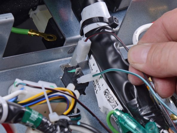
- Unplug the green ground barrel connector.
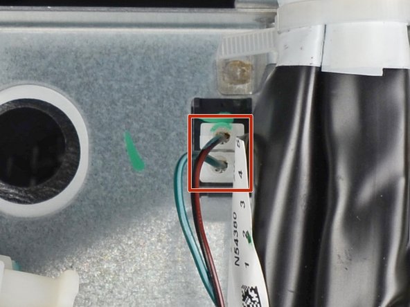
- Unplug the green and brown wires connected to the eco-throttle switch.
- Be sure to connect these wires to their respective sockets.
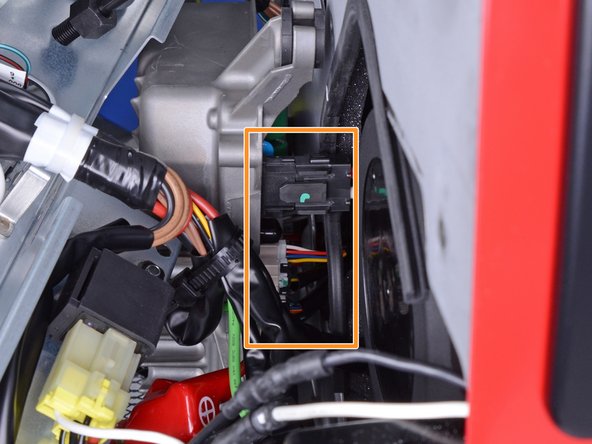
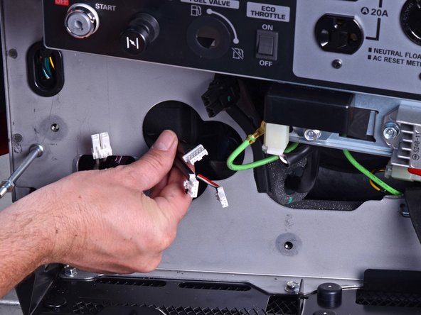
- Unplug the six-pin combination switch connector.
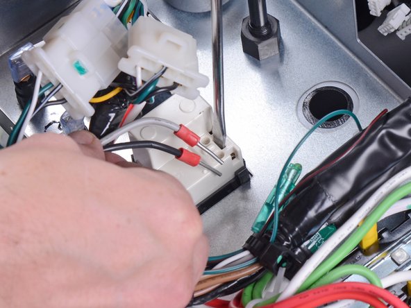
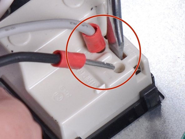
- Insert a flathead screwdriver into the slot behind the DC receptacle in order to release the receptacle wires.
- Pull and unplug the black and grey wires from the DC receptacle.
- Be sure to connect these wires to the proper sockets.
- Unplug the six-wire ignition control module connector.
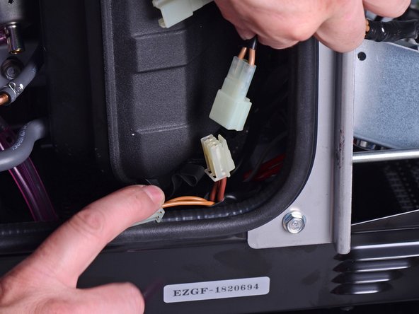
- Unplug the two winding connectors next to the air filter box.
- Do not plug in the new wire harness yet.
- Pull the existing wire harness out of the front frame.
- Thread the replacement harness through the same cutout.
- Route the three inverter connectors on the replacement harness through the double circular cutout in the front frame.
- Connect the two winding connectors to the new harness.
- The old wire harness should be completely removed.
- Compare your harness routing with the images in step 21. Be sure that the harness is securely fastened to the generator.