iMac Intel 21.5" Retina 4K Display 2019 RAM Replacement
ID: 136306
Description: This guide details removing the logic board in...
Steps:
- With the hinge free to move, the iMac will be unbalanced and hard to work on. Place an iMac service wedge, in the stand to stabilize the iMac.
- If you are using the iFixit cardboard service wedge, follow these assembly directions to put it together.
- Before beginning any work on your iMac: Unplug the computer and press and hold the power button for ten seconds to discharge the power supply's capacitors.
- Be very careful not to touch the capacitor leads or any exposed solder joints on the back of the power supply. Only handle the board by the edges.
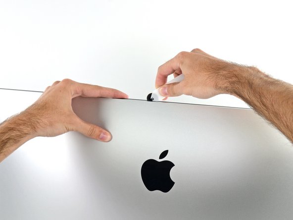
- Starting on the left side of the display, near the power button, insert the iMac Opening Tool into the gap between the glass panel and the rear enclosure.
- The hub on the iMac Opening Tool will keep you from pushing the wheel in too far. If using a different tool, insert no more than 3/8" into the display. Otherwise, you risk severing antenna cables and causing serious damage.
- Use the tool like a pizza cutter—roll it along the gap, cutting the foam adhesive in between the frame and display.
- Be sure to always push with the cutting wheel forward. If you pull, the wheel might get pulled out of the handle.
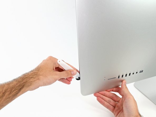
- Run the tool up along the left side of the display.
- Continue running the tool up around the top left corner.
- Cut the adhesive along the top left of the display.
- Continue along the top of the display.
- You may want to run the tool back and forth a few times to ensure you completely cut through the adhesive.
- Push the tool around the top right corner of the display.
- Push the tool down along the right side of the display.
- Finish pushing the opening tool to the bottom of the right side of the display.
- At this point, you'll want to run the tool back around the entire display, to ensure you cut as much adhesive as possible.
- While the opening tool cut most of the adhesive, the display will still be slightly adhered to the case. A plastic card will be necessary to free up the last of this adhesive.
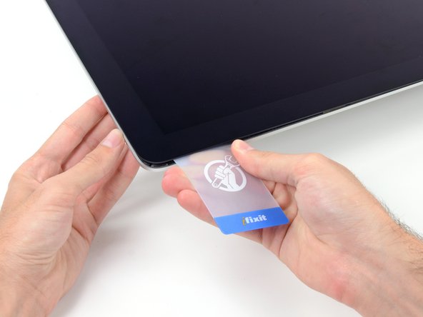
- Set the iMac face-up on a table.
- Starting from the top right corner of the iMac, wedge a plastic card between the display and frame.
- Be careful not to insert the plastic card more than 3/8", or you may damage internal components.
- Gently twist the plastic card sideways to create a gap between the display and frame.
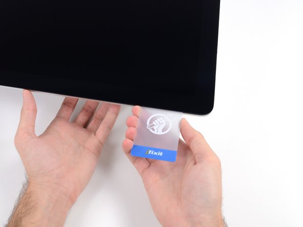
- Move slowly and be careful not to stress the display glass too much—you only need to make a gap of about 1/4".
- Slide the card toward the center of the display to cut any of the remaining adhesive along the top right corner of the iMac.
- Be sure to stop before the iSight camera, or you may damage it.
- Wedge the plastic card into the top right corner once again, and leave it there to prevent the adhesive from resticking.
- Insert a second plastic card into the gap between the display and frame near the top left corner of the iMac.
- Gently twist the card upward, slightly increasing the space between the display and frame.
- As with the other side, twist slowly to allow the adhesive time to separate, and be careful not to over-stress the display glass.
- Slide the plastic card toward the center.
- Stop sliding just before the iSight camera to avoid damaging the camera.
- Wedge the plastic card back into the top left corner.
- With both plastic cards inserted as shown near the corners, gently twist the cards sideways to increase the gap between display and case.
- If there are any sections that seem to stick and won't separate, stop twisting and use one of the cards to cut the remaining adhesive.
- Begin to lift the top of the display up from the frame.
- Only lift the display a few inches—the display data and power cables are still connected to the logic board.
- Lift the display up enough to have easy access to the connector, but not so much that you stretch the cables and stress their connections (about 8").
- Hold the display with one hand while using your other hand to unplug the display power cable.
- Continuing to support the display with one hand, flip up the metal retaining bracket on the display data cable.
- Carefully pull the display data cable from its socket on the logic board.
- Be sure to pull the display data cable connector straight out of its socket, keeping it parallel to the motherboard, to avoid damaging it.
- Lift the display up to a near-vertical position.
- At this point there is still a strip of adhesive along the bottom of the display that will hold the display to the frame like a hinge. You can loosen this adhesive by working the display up and down a few times.
- Be very careful not to touch the capacitor leads or any exposed solder joints on the back of the power supply, indicated here. Touching it risks a high voltage shock from the many large capacitors attached to the board.
- If necessary, a plastic card can be used to cut any remaining sections of the bottom adhesive strip.
- Lift the display up from the frame and remove it from the iMac.
- It may be necessary to slowly lift from one side to peel against the remaining adhesive.
- Be very careful handling the display—it's big, heavy, and made of glass.
- After the adhesive is cut, it cannot be used to re-seal the display in place. Follow this guide to replace the adhesive strips that secure the display to the rear enclosure.
- Remove the following five Phillips screws holding the lower support bracket in place:
- Four 3.2 mm screws
- One 1.7 mm screw
- You may need to peel up the display adhesive lining the bottom edge of the iMac enclosure to access the screws.
- Remove the lower support bracket (a.k.a. "chin strap") from the iMac enclosure.
- Remove the following T10 Torx screws securing the hard drive brackets to the iMac:
- Two 21 mm screws
- One 9 mm screw
- One 27 mm screw
- Remove the left and right hard drive brackets from the iMac.
- The next few steps bring your hands close to the exposed face of the power supply. Do not touch the face of the power supply or any of the exposed solder. Touching it risks a high voltage shock from the many large capacitors attached to the board.
- Use the tip of a spudger to push each side of the power button cable connector and gently walk it out of its socket.
- Use the tip of a spudger to push each side of the power supply control cable connector and gently walk it out of its socket.
- Remove the two 7.2 mm T10 Torx screws securing the power supply to the rear enclosure.
- In newer model iMacs these are 7.2 mm T8 Torx screws.
- During reassembly, be careful not to trap the power button wire behind the board.
- When working on the power supply, be very careful not to touch the capacitor leads or any exposed solder joints on the back of the power supply. Only handle the board by the edges.
- Tilt the power supply forward.
- Pull the power supply slightly up and out from the rear enclosure.
- Rotate the power supply counterclockwise, lifting the right side up about an inch higher than the left.
- Slide the power supply to the right to clear the screw posts on the rear enclosure.
- Rock the power supply forward and remove it from its recess in the rear enclosure.
- Do not try to completely remove the power supply from the iMac yet—it is still connected to the logic board.
- Be very careful not to touch the capacitor leads or any exposed solder joints on the back of the power supply. Only handle the board by the edges.
- Flip the power supply over to access the DC power cable connection behind the logic board.
- Squeeze the tab on the back side of the DC power cable connector and pull it straight out of its socket on the back of the logic board.
- You may find it helpful to set the iMac down on its back for the next couple of steps.
- Use the flat end of a spudger to press the clip on the side of the AC inlet cable connector inward.
- While pressing on the release clip with the spudger, grasp the AC inlet cable, and pull the connector straight out of its socket.
- Remove the power supply from the iMac.
- Gently pull the fan cable connector straight away from its socket on the logic board.
- Remove the three 10 mm T10 Torx screws securing the fan to the rear enclosure.
- The uppermost screw has a rubber standoff adhered to its head to support the display—leave this in place.
- Remove the fan from the iMac.
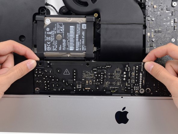
- Lift the hard drive from the edge nearest the logic board and pull it slightly out of its recess.
- The hard drive is attached by a single SATA power/data cable—do not attempt to fully remove it from the iMac yet.
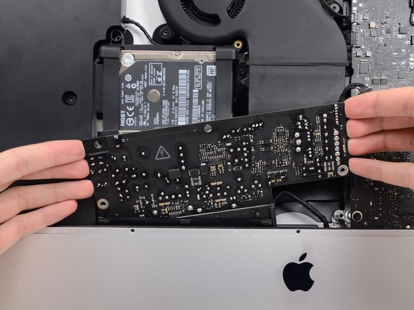
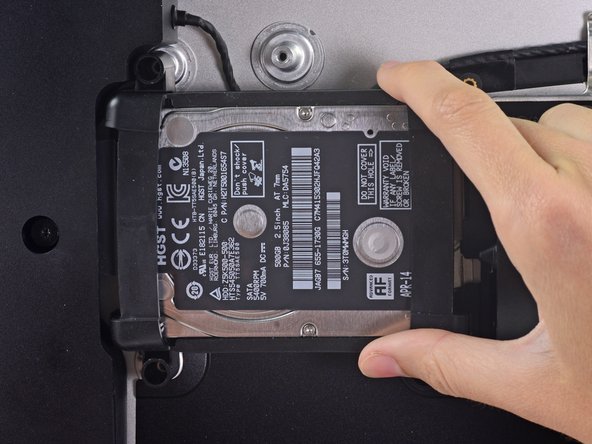
- Use a spudger to disconnect the single SATA power and data combo cable by gently prying its large plastic connector away from the hard drive.
- Remove the hard drive assembly from the iMac.
- Remove the 7.3 mm T8 Torx screw securing the hard drive tray to the rear enclosure.
- Remove the SATA cable from the clips on the back of the hard drive tray.
- Remove the hard drive tray.
- Gently pull the left speaker cable straight out of its socket on the logic board.
- De-route the left speaker cable by pulling it straight up out of the retaining clip in the back of the rear enclosure.
- Similarly to the previous step, de-route the SATA and power cables by pulling the braid straight up out of the retaining clip.
- Peel up the piece of tape connecting the left speaker connector to the SATA power and data cables.
- Flip up the metal retaining bracket on the FaceTime camera cable connector.
- Pull the iSight camera cable straight out of its socket on the logic board.
- This is a delicate connector that can be easily damaged.
- Remove the two 4.0 mm T5 Torx screws securing the four AirPort/Bluetooth antenna connectors.
- Rotate the top of the AirPort/Bluetooth connector bracket away from the logic board, then lift the bracket straight up and remove it.
- During reinstallation, make sure to line up the tabs on the bottom of the bracket with the holes in the EMI shield. These tabs should seat fully inside the holes before the bracket is installed.
- Use the point of a spudger to pry all four antenna connectors straight up from their sockets and disconnect them from the AirPort/Bluetooth card.
- Use a pair of tweezers or your fingers to pull the right speaker cable connector straight down and out of its socket on the logic board.
- Use the flat edge of a spudger to pry the headphone jack cable connector from its socket on the logic board.
- Push the cable slightly to the right to move it out of the way of the logic board.
- Peel off the tape covering the exhaust duct.
- Remove the following T8 Torx screws securing the exhaust duct to the rear enclosure:
- Two 6.2 mm screws
- Two 4.7 mm screws
- Use the tip of a spudger to flip open the retaining flap on the microphone ribbon cable ZIF socket.
- Be sure you are prying up on the hinged retaining flap, not the socket itself.
- Use tweezers to gently pull the microphone ribbon cable straight out of its socket.
- Remove the four 7.3 mm T8 Torx screws securing the logic board to the rear enclosure.
- When removing and installing the logic board, take care not to damage the delicate microphone ribbon cable at the bottom left of the board.
- Tilt the top of the logic board away from the rear enclosure.
- As you tilt the logic board, pull the right speaker connector to the right and out of the way of the board.
- Lift the logic board straight up and out of the iMac.
- Be careful not to snag the board on any of the rear enclosure's screw posts.
- When reassembling your iMac, be very careful to align the exterior I/O ports correctly. The logic board can sit crooked even when secured with all its screws.
- Use a USB flash drive and/or ethernet cable to keep the logic board seated correctly while you tighten the screws.
- Handling the board by the edges, flip the logic board over to access the two RAM modules.
- Use a T4 Torx driver to remove the four 2.4 mm screws securing the RAM shield.
- Remove the RAM shield.
- Two clips secure the RAM module in place, one on each side. Using your fingers, spread the clips away from the RAM module.
- When released, the RAM module will pop up at a slight angle.
- Lift the RAM module to an angle of about 30 degrees and slide it out.
- When handling the RAM module, touch only the outside edges. Take care not to touch the gold-colored contact points along the bottom edge.
- To install a new RAM module, slide it in place at about the same angle until it is snug, and then swing it downward until the two clips snap into place.
- The original RAM module closer to the logic board may have a thermal pad adhered to its top side (facing away from the logic board, between the two DIMMs).
- If your RAM includes a thermal pad, peel it off and transfer it from the original RAM stick to your replacement RAM before you install it in the lower slot.