Samsung Galaxy S9 Headphone Jack Replacement
ID: 136569
Description: Use this guide to remove the headphone jack on...
Steps:
- Before you begin, switch off your phone.
- Apply a heated iOpener to a long edge of the phone to loosen the adhesive beneath the rear glass. Apply the iOpener for at least two minutes.
- You might need to reheat and reapply the iOpener several times during the removal procedure to get the adhesive warm enough to cut. Follow the iOpener instructions to avoid overheating.
- The adhesive of the Samsung Galaxy S9 is very strong. A hair dryer, heat gun, or hot plate may also be used if you aren't able to open the device with the iOpener. Be careful not to overheat the phone—the AMOLED display and internal battery are both susceptible to heat damage.
- In the following steps, you'll be cutting through the adhesive securing the back cover.
- The adhesive in the inside of the back cover is laid out as seen in the image.
- You'll be slicing through the adhesive in the areas shown:
- Thick portions of adhesive
- Thin areas of adhesive
- Avoid prying or slicing in this area, to protect the fingerprint sensor flex cable.
- If the phone's rear glass is cracked, the suction cup may not stick. Try lifting it with strong tape, or superglue the suction cup in place and allow it to cure so you can proceed.
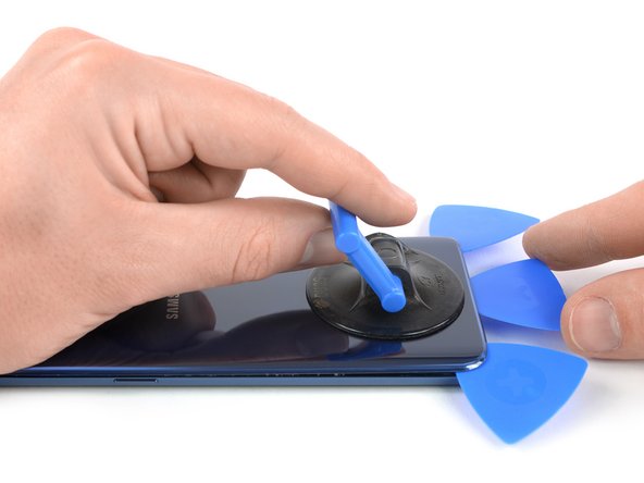
- Press a suction cup onto the back cover.
- Lift the back cover's bottom edge with your suction cup, opening a slight gap between the back cover and the frame.
- This may require a significant amount of force, but you only need to open a very slight gap with the suction cup to insert your tool. If you have trouble, apply more heat to further soften the adhesive, and try again. The adhesive cools very fast, so you may need to heat it repeatedly.
- Insert an opening pick in the gap you created and slide it to the bottom right corner.
- Insert a second opening pick and slide it to the bottom left corner.
- Insert a third opening pick to prevent the adhesive from resealing during the rest of the removal procedure.
- While inserting only the tip of the opening pick, slide it from the bottom left corner along the side to the top.
- Slide the pick around the top corner and leave it there to prevent the adhesive from resealing.
- Slide the opening pick from the bottom right corner along the side to the top.
- Apply more heat if the adhesive becomes hard to cut. During the removal process, the back cover is under tension all the time and is likely to break if the adhesive isn't softened enough.
- Slide the opening pick around the corner and cut the remaining adhesive at the top of the phone.
- Don't open the phone all the way yet. The fragile fingerprint sensor cable still connects the back cover to the motherboard.
- Carefully lift the side of the rear glass where the volume button is located.
- Use the edge of a spudger to pry up and disconnect the fingerprint sensor flex cable.
- Remove the rear glass.
- When reassembling follow this guide to replace the adhesive and reinstall the rear glass.
- In case you want to replace your rear glass follow this guide to transfer the rear camera bezel including the fingerprint.
- Remove the eight 4 mm Phillips #00 screws.
- Insert an opening pick under the right side of the plastic cover containing the NFC antenna and charging coil.
- Twist or pry to release the plastic clips securing the cover.
- Insert an opening pick under the left side of the plastic cover.
- Twist or pry to release the plastic clips securing the cover.
- Remove the plastic cover containing the NFC antenna and charging coil.
- Use the flat end of a spudger to pry up and disconnect the battery flex cable.
- Remove the two 4 mm Phillips #00 screws holding the plastic cover in place.
- Remove the plastic cover from the motherboard.
- Remove the five 3.5 mm Phillips #00 screws.
- Insert an opening pick underneath the top edge of the loudspeaker assembly.
- Use the opening pick to pry up the loudspeaker assembly.
- Remove the loudspeaker assembly.
- Remove the 3.5 mm Phillips #00 screw.
- Use the flat end of a spudger to pry up and disconnect the headphone jack flex cable.
- Use a pair of tweezers to remove the headphone jack.