Check the Jura ENA micro 9 brew assembly
ID: 136633
Description: The brew assembly in ENA models is basically...
Steps:
- Pull out the power plug!
- Remove all attachments, such as the water reservoir, coffee grounds drawer, and bean compartment lid.
- Remove all coffee beans.
- The top covers do not necessarily have to be removed for all repairs. However, it is indispensable for thorough cleaning. It may be easier to loosen the top covers if the side panels are removed first. The process is somewhat tricky.
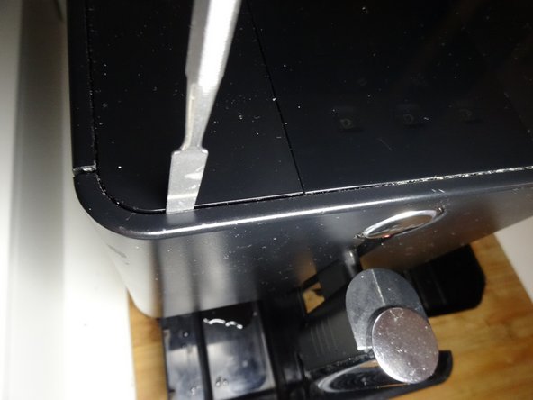
- Pry the central ventilation cover up.
- Use the spudger to press in on both sides of the marked area. Then the front cover around the on / off switch is unlocked. You can then lift it up at the front and pull it out at an angle.
- If the side openings for the spudger cannot be found, the model is slightly different. With this version you have to insert the spudger into the gap between the front panel and cover, about 3 cm from the edge and then push it firmly towards the center to unlock. At the same time, lift the cover a little at the front.
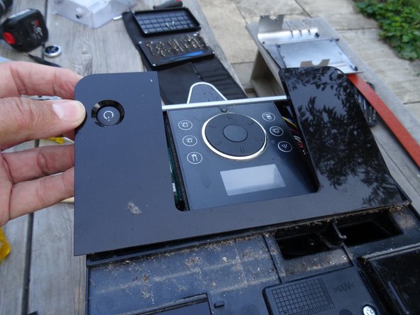
- Flip up the front cover.
- Remove the cover. In the model with the side holes, you can pull them out at an angle to the front. With the other model, you have to push it back a little to unhook it, then lift it up.
- This is what it looks like when the two lids are gone. A lot of dirt built up.
- The side parts are pushed out to the rear. However, they are secured with two screws and a lock at the top and a wedge-shaped catch on the sides.
- Unscrew the two T15 Torx screws that secure the side panels at the top.
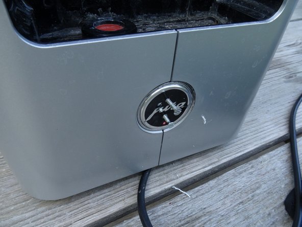
- The lock is located under the Jura badge on the back. Turn it counterclockwise about 20 degrees, then you can remove it.
- Unfortunately, this one is very stuck. Nothing helped with this device, no suction cup or stiff adhesive tape. Here it is opened with a somewhat more rustic method:
- Two small holes were drilled a few millimeters deep, then two small screws were screwed in. The badge could finally be turned and removed with a pair of pliers.
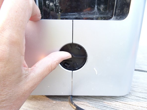
- This is what it looks like underneath. The lock is secured with an oval head screw. It looks like a rivet. To open you need a special oval head bit, in an emergency you can use pliers.
- Remove the oval head screw.
- Push the lock firmly upwards as far as possible.
- The side parts are held at the top and bottom with three hooks each. Therefore, they have to be moved backwards to detach them. However, they are secured against shifting with wedge-shaped notches at the front. The next step shows how they can be solved.
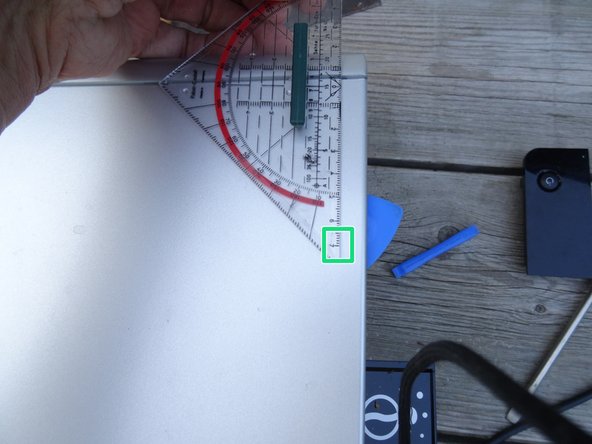
- The notches must be lifted out of the openings. They are located on both sides at the top and bottom about 1.5 cm from the edge and 7 cm from the front edge.
- This is what the wedge-shaped notches look like
- Lay the machine on its side.
- Pry the side panel about 7 cm from the front edge, about 3 mm high. This will cause the catch to come out of its opening. Use a strong tool, preferably one made of plastic.
- Position of the wedge-shaped notch: 7 cm from the front edge, 1.5 cm from the top or bottom edge.
- Leave the tool in place. Insert an opening pick 7 cm from the front edge so that the wedge-shaped notch can no longer engage in its opening. Pull out the tool.
- In the same way, insert another opening pick on the opposite edge.
- Now both notches are free and the side part can be moved in the next step.
- Push the side panel firmly backwards. It may get stuck a bit and you need to use a plastic pry tool to help.
- Take off the side panel and set it aside.
- Repeat for the other side panel.
- Release the catches on the top of the inner cover.
- Flip the inner cover down and lift it out. The brew group becomes now visible.
- The cover is not present on all models.
- The third picture shows a view of the other side.
- Peel off the silicone tube with a pair of tweezers.
- Unscrew the Torx T20 machine screw in the middle on the left.
- Access to the screw is obstructed by the filling funnel. A long shaft screwdriver will help.
- Unscrew the Torx T20 machine screw in the middle on the right.
- Unscrew the Torx T15 screw at the bottom right.
- The brew assembly is now free. Gently tip it out at the bottom and remove it from the device.
- When assembling, first insert the inlet nozzle at the bottom, then you can slide in the brew assembly
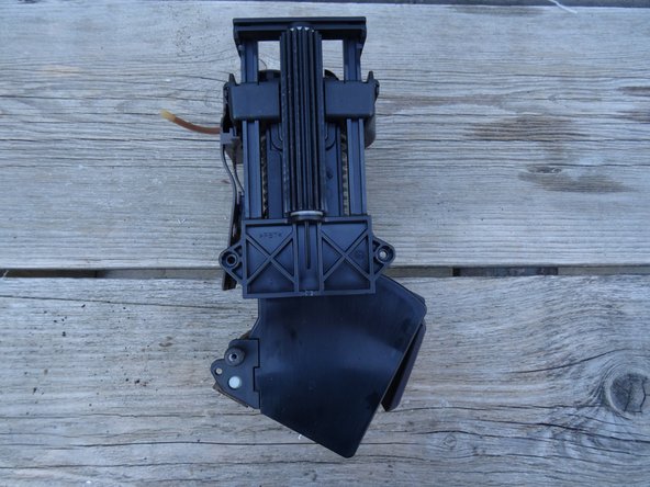
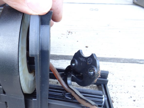
- The drive is on the left, the pulp shovel can be seen on the right.
- Remove the two Torx T15 screws that hold the drive in place.
- Disengage the brown pulp shovel at the top.
- Pull the pulp scoop down and out and set it aside.
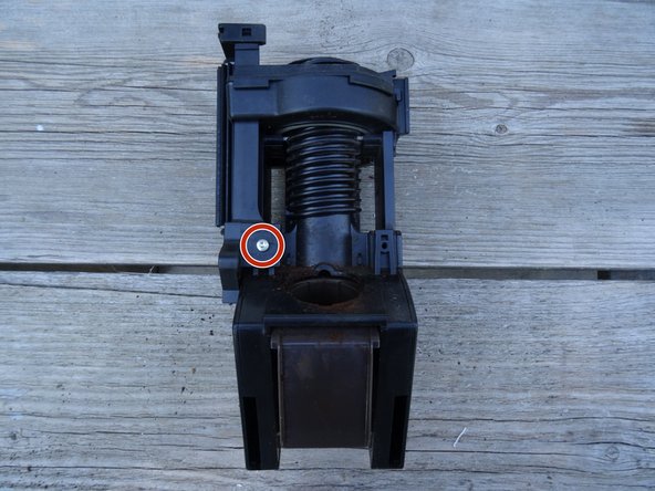
- Remove the two Torx T20 machine screws that secure the drive to the upper piston.
- Lift away the top cover with the coffee dispensing hose
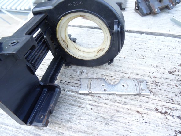
- Pull the metal retaining plate out of the upper piston. Note the orientation for later assembly. The top cover has a pin that must fit into the corresponding hole on the plate.
- Turn the drive until it detaches itself from the brew assembly upwards
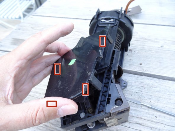
- In this step the two side covers are removed. They are each locked in four places, some of which are hidden.
- Use your finger or a spudger to push the catches aside and lift the cover off.
- Repeat for the cover on the other side.
- In this step, the two guide plates on the left and right are removed
- There are two loose metal rings under the guide plates for guidance. Don't lose it.
- Lift the two guide plates away. For later assembly, take a close look at how they are attached to the top of the piston.
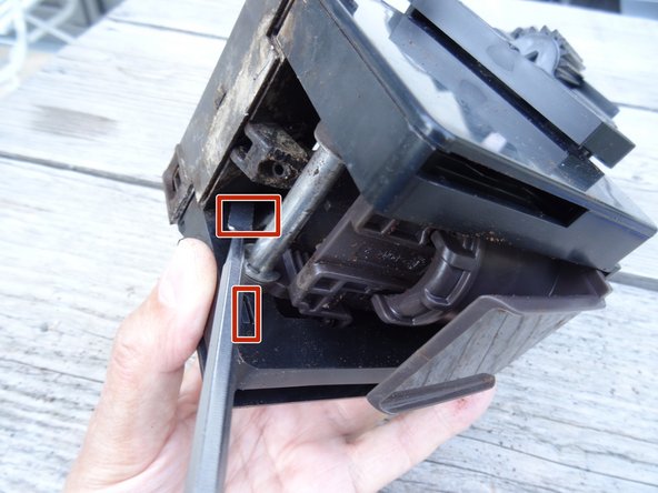
- Slide the drainage valve down and out.
- Here you can see the current status
- In the following step the lower piston is released.
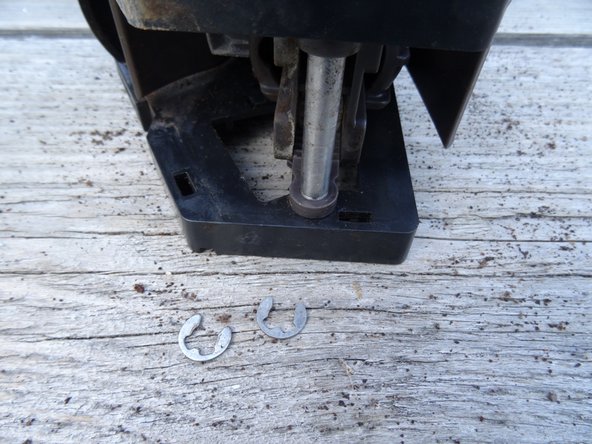
- The axis of the lower piston is secured with two ring cotter pins on the left and right. Use a sharp tool and pry out the two cotter pins.
- Push out the axle.
- Take a close look at the orientation of the piston, it will have to be reinstalled later. It has an indentation for the docking connector that has to fit.
- Now you can turn the mechanics a little to the side and push out the piston. Further dismantling is possible, but not necessary. Make sure that there are two more metal rings at the top under the fork, these should stay in and not get lost.
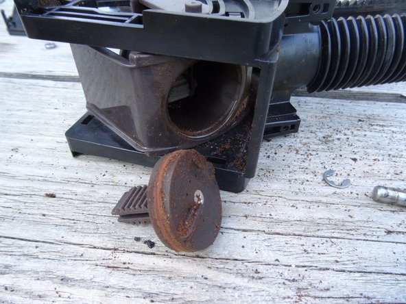
- Unscrew the Phillips screw in the sieve of the lower piston and disassemble the piston.
- Unscrew the Phillips screw on the sieve of the upper piston and lift the sieve off.
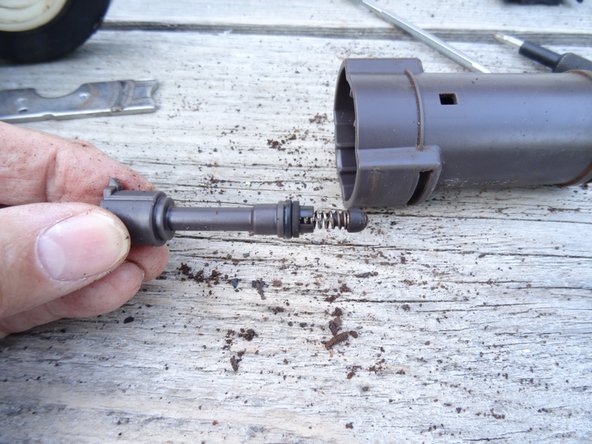
- Depress the catch on the side of the plunger and pull the crema valve up and out.
- The brew assembly is now dismantled. Now you have to clean all parts thoroughly, replace the seals on the upper and lower pistons, and thinly grease them and the cylinder wall with food-safe silicone. Now the drainage valve should also be revised.