Lenovo IdeaPad Flex 5-1570 Webcam Replacement
ID: 139886
Description: The webcam is a typically small camera attached...
Steps:
- Remove the ten 5 mm Phillips #00 screws that are holding the back panel on.
- Use a spudger to pry open the back case at the two hinge cutouts.
- Gently use the plastic opening tool around the edges of the laptop to pry up the clips holding the rest of the back panel.
- Once all the clips have been disengaged, lift off the back cover.
- Remove the two 5 mm Phillips #00 screws that secure the battery in place.
- Using your fingers, grasp the entire bundle of wires to pull the battery cable from its connector. This will cut off power to the motherboard.
- Be sure to apply even pressure across the wires and connector to not damage the battery cable.
- Remove the battery from the device.
- Remove the three 5 mm Phillips #00 screws that secure the hard drive.
- Using your hands, gently pull the hard drive back, sliding it out from the port.
- Remove the two 5 mm Phillips #00 screws that secure the fan in place.
- Using your hands, remove the wire that is wrapped around the base of the fan.
- Disconnect the wire holding the fan and the motherboard together.
- Remove the fan from the device.
- Using the Phillips #00 screwdriver, remove five 5 mm screws.
- For proper screwdriver technique, please visit the Screwdriver Best Practices guide.
- Carefully remove the heatsink from the device.
- During reassembly, don't forget to apply thermal paste onto the heatsink. For proper technique on thermal paste application, please visit the How to Apply Thermal Paste guide.
- Using the iFixit nylon tipped tweezers, disconnect the wire that connects the speakers to the motherboard.
- Using your hands, gently pull the left speaker up and out of the device.
- Repeat the previous step for the other speaker and remove the speakers from the device.
- Using the Phillips #00 screwdriver, remove the three 5 mm Phillips #00 screws securing the motherboard.
- Disconnect the auxiliary port cable from the motherboard.
- Using a plastic opening tool, unlock the four ZIF connectors of the flat cables.
- Lift up the connector locking tab and disconnect the cables from the motherboard.
- Disconnect the display cable from the motherboard.
- Using the plastic opening tool, unlock the connector for the side ports panel and disconnect the cable from the motherboard.
- Carefully lift and remove the motherboard from the device.
- Using the Phillips #00 screwdriver, remove the four total 5 mm screws from the left and right hinges (two screws on each hinge).
- For proper screwdriver technique, please visit the Screwdriver Best Practices guide.
- Disconnect the display assembly from the rest of the device.
- Flip the display assembly so that the screen is facing you.
- Using a spudger, remove the screw cover to expose two screws. Repeat this step for the cover on the right side of the screen.
- The spudger may not provide enough prying power to remove the screw covers. If need be, carefully use the metal spudger to complete this step.
- Using the Phillips #00 screwdriver, remove the two 3 mm screws from the display (one screw on each side).
- Using the opening picks and a plastic opening tool, remove the middle screw cover at the bottom of the display assembly to expose three screws.
- Using the plastic opening picks and tools may not provide enough prying power. If need be, use the metal spudger to remove the screw covers.
- Use the Phillips #00 screwdriver to remove three 3mm screws from the display assembly.
- Carefully insert the opening picks into the edge of the display and display cover.
- Work your way around the screen to remove it from the assembly.
- You may want to use a heat gun or hair dryer to heat up the adhesive holding the screen to the rest of the display assembly. These adhesive strips are located approximately 2 cm away from left and right edges of the screen and 3 cm from the top. This video shows where these strips are located.
- Alternatively, using the iOpener may heat up the adhesive enough to remove the screen from the rest of the display. Please visit the iOpener Instructions guide for more details on properly heating the iOpener.
- Lift the screen up and away from the rest of the display assembly.
- As stated in the previous step, there are two strong adhesive strips holding the screen to the rest of the display assembly, so please proceed with caution when separating the screen from the assembly.
- Flip the screen over so that the backside of the screen is facing you.
- Remove the tape covering the webcam and disconnect the webcam from the screen.
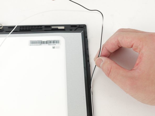
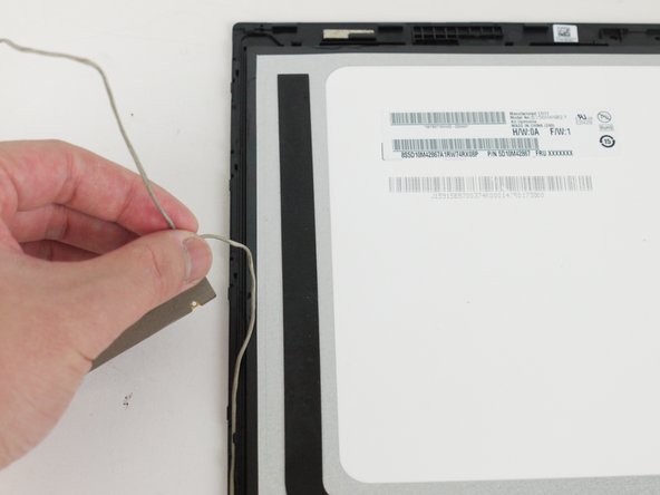
- Unravel the cables along the left and right sides of the screen.
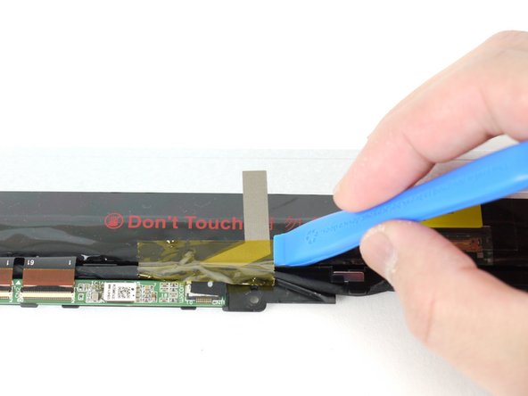
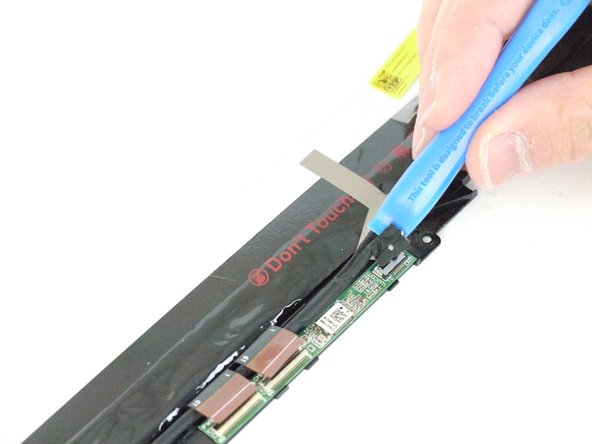
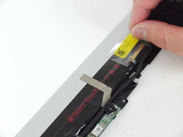
- Using a spudger, remove the yellow tape on the bottom right corner of the screen.
- Remove the yellow tape using your fingers or a plastic opening tool.
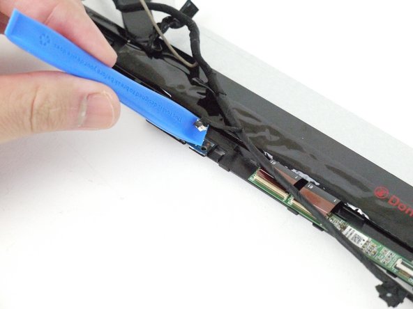
- Using the plastic opening tool, remove the black tape from the device.
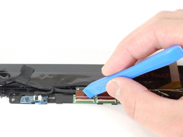
- Using the same tool, unlock the ZIF connectors and disconnect the flat cables.
- Using the plastic opening tool, disconnect the cable from panel.
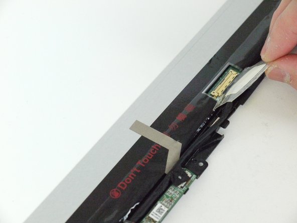
- Use the plastic opening tool to get under the piece of tape connecting the webcam cable to the display assembly.
- Grip the piece of tape with your fingers and pull it away to disconnect the cable.
- Disconnect the webcam and remove it from the device.