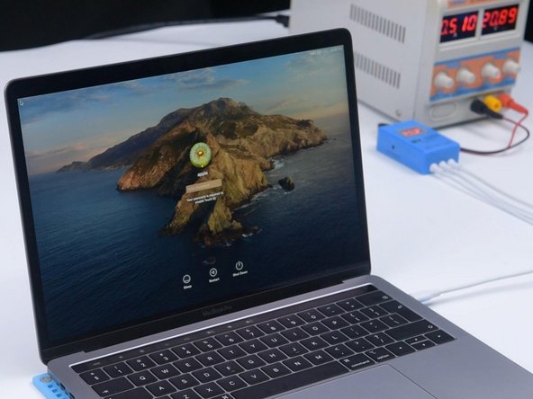
Repair For MacBook Pro A1989 That Won't Turn On
ID: 139928
Description:
Steps:
- Press the power button. The MacBook won’t turn on.
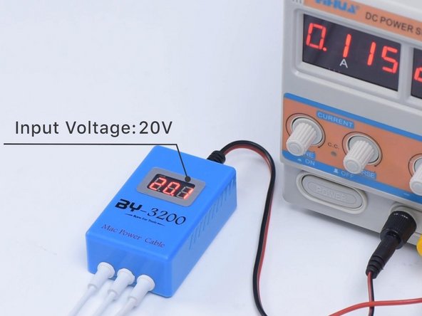
- Plug in the BY-3200 power cable, and set the input voltage to 20V.
- In this case the amperage is 0.047A.
- Unplug the power cable. Next, we need to disassemble the MacBook and test.
- Remove the 6 pentalope screws and disconnect the battery connector flex cable.
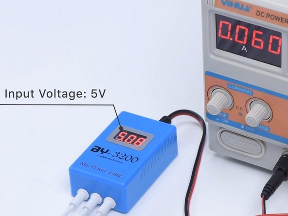
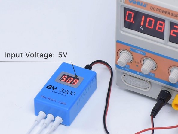
- Plug in the BY-3200, and set the input voltage to 5V.
- The current reading on the DC Power Supply is 0.059A.
- In this case power supply says the motherboard is only using 5V, which is abnormal.
- The normal power supply should read 20V. This indicates that the motherboard has malfunctioned.
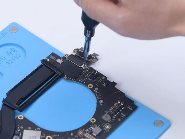
- Next we will remove the motherboard and install the power connector flex cable.
- The motherboard number is 820-00850-07.
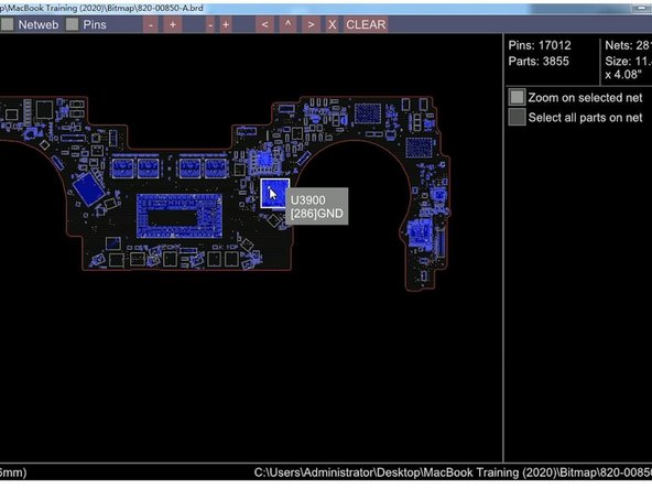
- Open the schematic diagram and bitmap.
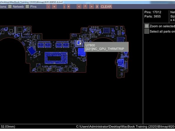
- U3900 is the T2 chip. U7800 is the power chip.
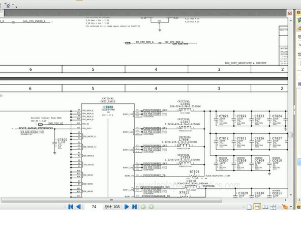
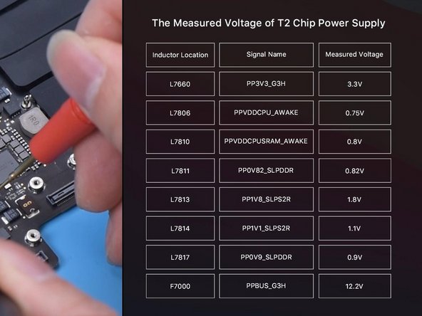
- Measure the standby voltage of the T2 chip, which is supplied by the U7800. Find U7800 on the schematic diagram.
- This table shows the standby voltage of the T2 chip.
- Plug in the power cable.
- The motherboard's current stops at 0.06A, and the input voltage is only 5V.
- Measure the power supply of the motherboard.
- The measured voltage values are normal. It can be judged that the power supply circuit of the motherboard is good.
- Next, we need to determine if the fault (voltage failing to increase) is caused by T2 chip data problems.
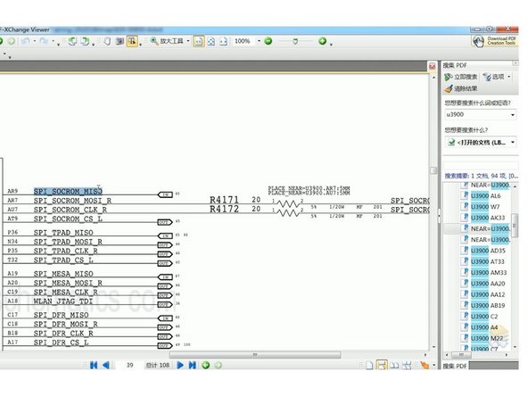
- Find the T2 chip on the bitmap, and the location name is U3900. Search U3900 on the diagram and find the ROM chip for T2.
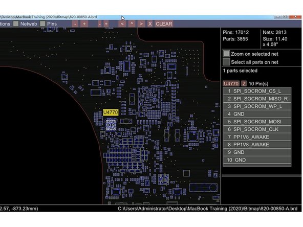
- Copy signal SPI_SOCROM_MISO. Find the SoC ROM, and the location name is U4770. Find U4770 on the bitmap.
- Find the SoC ROM (U4770) on the motherboard. Remove the SoC ROM chip with a Hot Air Gun at 430℃.
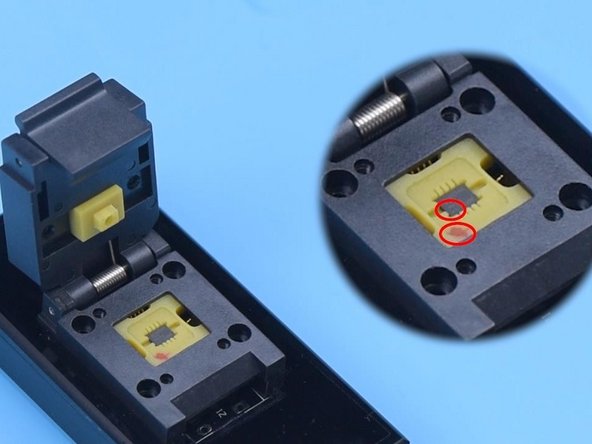
- Get the BY-T200 and write the new SoC ROM data. Attach the chip to the seat of BY-T200. Pin 1 of the chip must align with the red dot on the tool.
- Then connect BY-T200 with the computer.
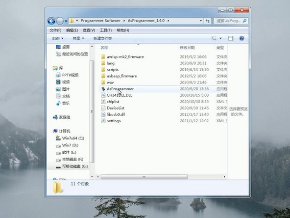
- Install the driver and open AsProgrammer.
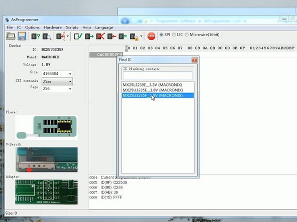
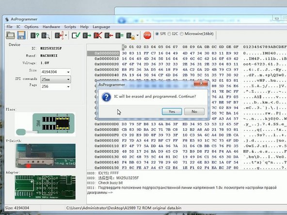
- Click Read ID and select MX25U3235F_1.8V.
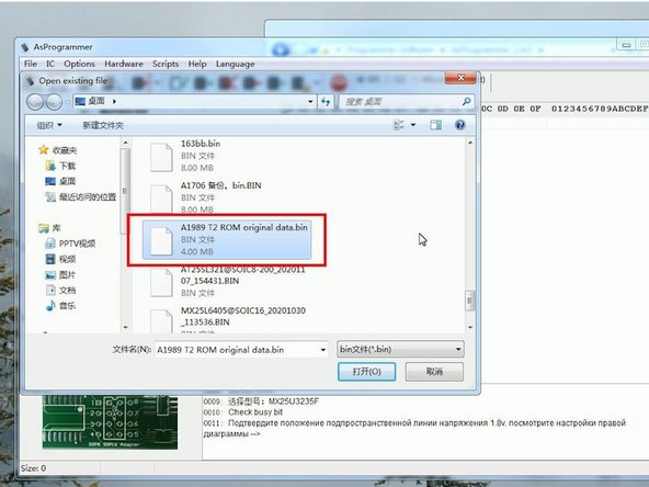
- Click Open file and select A1989 T2 ROM original data.bin.
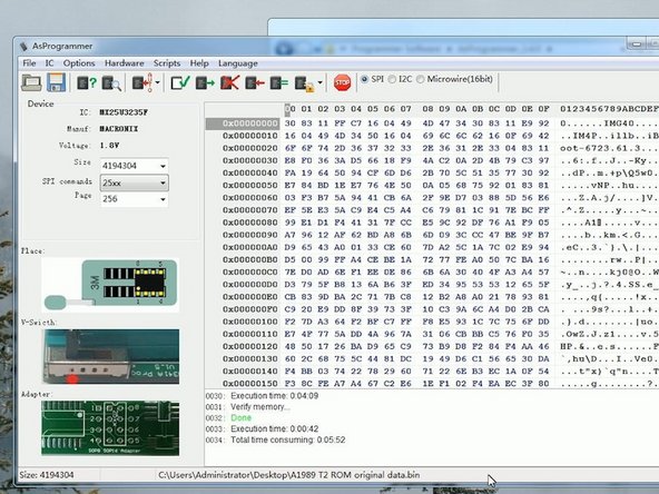
- Click Auto Program and click Yes.
- Data writing has been completed.
- Unplug BY-T200. Solder the chip back to the motherboard.
- Plug in the power cable. The BY-3200 shows an increase in input voltage from 5V to 20V.
- The current jump on the DC power supply is normal, which indicates that the motherboard is turned on.
- Disconnect the power cable and install the motherboard. Plug in the power cable.
- The MacBook is turned on and can enter the system.
- Lastly, reassemble the MacBook by following steps 1-5 in reverse.
- Connect the battery flex cable and put the back cover on.
- Plug in the power cable and press the power button. The MacBook is turned on and can enter the system. The fault has been cleared.