Xbox 360 Wireless Controller 3D Analog Sensor Replacement
ID: 14168
Description: Your controller analog stick may undergo wear...
Steps:
- Depress the battery release button on the top of the controller.
- Remove the battery holder from the controller.
- The standard option for Xbox 360 Wireless Controllers Battery Packs is AA batteries. A rechargeable battery is also available, but both battery options are removed from the controller in the same way.
- Use a pair of tweezers to peel the barcode sticker from the battery compartment.
- Remove the seven 9.3 mm T8 Security Torx screws securing the rear case to the front case.
- Insert a Spudger between the front and rear cases along the left edge of the controller.
- Rotate the spudger toward the front of the controller, prying the two cases apart.
- Insert a spudger between the front and rear cases, near the headphone jack.
- Rotate the spudger toward the front of the controller to pry the two cases apart.
- Grasp the controller by the battery compartment and the headphone jack.
- Lift the battery compartment away from the headphone jack, separating the rear case from the front case and logic board.
- The battery contact springs are held in place by slots in the battery housing in the rear case. Be sure to realign them properly during reassembly.
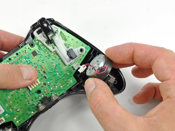
- Use the flat end of a spudger to remove the vibration motor cable, moving it upward from its socket on the logic board.
- Lift the vibration motor out of the front case.
- Remove the vibration motor from the other side of the controller using the same method previously described.
- The left motor has significantly more counterweight than the right motor.
- Lifting from the headphone jack and power plug, remove the logic board from the front case.
- Using your thumb and forefinger, push the left trigger toward the right side of the controller. Simultaneously push the trigger control arm in the opposite direction.
- The trigger has a peg that fits into a slot in the trigger arm. Be sure to push far enough so that the peg clears the slot.
- Push the trigger arm downward.
- Insert the edge of a spudger in between the trigger and the trigger assembly near the left edge. Pry the housing away from the catch on the trigger.
- Using the previously described technique, pry the housing on the right edge away from the trigger.
- Rotate the trigger away from the logic board, past its housing.
- Using a spudger, pry the trigger spring off its peg on the trigger housing.
- Pull the trigger spring out of the trigger.
- Slide the trigger toward the right side of the logic board, and rotate it clockwise.
- Remove the right trigger from the logic board.
- To remove the left trigger from the logic board, follow the procedure previously described for the right trigger.
- To remove the trigger control, only one has to be removed as it is over the analog sensor (left side).
- Optional: It is easier to remove both, so as to avoid burning or melting the plastic while working.
- The part should easily slide out once the solder is properly removed. If not, go back and check for solder left in the joints.
- Heat and suck up the solder.
- Remove analog sensor and place new part.
- The part should easily slide out once the solder is properly removed. If not, go back and check for solder left in the joints.
- Hold part in place and make a quick solder to hold it up in place.
- Now solder all joints and follow in reverse.