Sharper Image Razor Scooter (Wheel-e Series) Teardown
ID: 14175
Description: Introduction: In this guide, we disassemble the...
Steps:
- In order to conduct this teardown you will need (depicted from left to right):
- 1 Hammer
- 1 Pair of Channel Lock Pliers
- 1 Flathead Screwdriver (for prying)
- 1 Pair of Needlenose Pliers
- 1 Metric Allen Key Set
- 1 Pair of Snapring Pliers
- Start by pressing the lock lever with your thumb and unfold the scooter into riding position.
- Take the top of the scooter and open the handlebar lock to expose the small screw underneath. (Picture 1)
- Using a 3mm allen key unscrew the single retaining screw. (Picture 2)
- Once the screw is removed the clip tightening screw can be removed by hand freeing the whole retaining clip. (Picture 3)
- Now that the retaining clip has been freed, slide it off towards the handlebars. (Picture 1)
- Once the retaining clip is removed the handlegrip "T" will now easily slide out of the scooter base. (Picture 2)
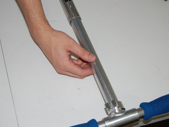
- Moving down the remaining scooter shaft, use a 5mm allen key to remove the lower retaining ring. (Picture 1)
- Now remove the remaining scooter shaft by unscrewing it from the the wheel and axle. (Picture 2)
- Hint: Hold the front wheel while unscrewing the shaft to prevent the axle from spinning.
- Using your hand unscrew the first nut on the axle. (Picture 1)
- Note: This is the jam-nut used to stop the axle from falling apart.
- Now using the Channel Lock Pliers remove the axle retaining nut. (Picture 2)
- Hint: You may have to hold the front wheel to prevent the whole assembly from rotating.
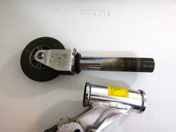
- The axle is now able to be slid out. (Picture 1 & 2)
- Note: this piece could be covered in grease.
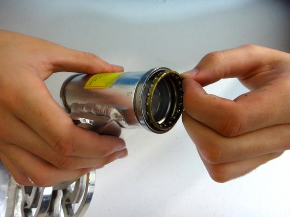
- Now carefully remove the bearing sitting inside of the axle housing. (Picture 3)
- There will also be a bearing on the axle itself which can also be easily slid off. (Picture 1)
- Now that the axle is free the front wheel can easily be removed using two 5mm allen keys. (Picture 2)
- Hint: If you only have one 5mm allen key, the 5mm allen key and the pair of needle nose pliers can be used instead of two allen keys.
- The rear wheel assembly can now be removed using a 5mm allen key. Use the same process as that to remove the front wheel in Step 8. (Picture 1)
- The one screw will disconnect the rear wheel and the wheel-e bar from the scooter frame. (Picture 2)
- The brake mechanism is attached to the base by a steel pin. This pin is difficult to remove, but would be possible with a large press. (Picture 1)
- Caution: It is our recommendation that you do not attempt to remove this pin unless absolutely necessary. It will be very difficult to get back in place.
- A torsion spring controls the actuation of the brake. (Picture 2)
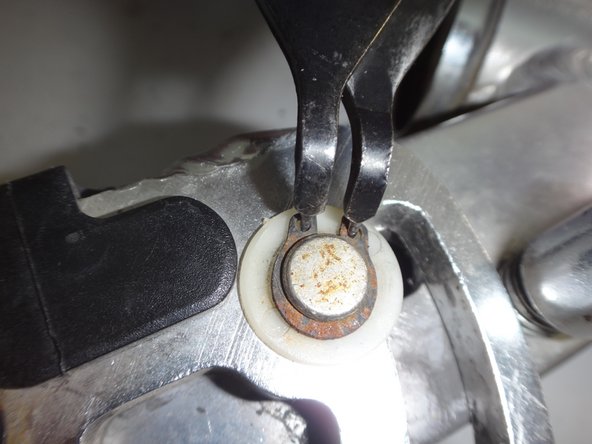
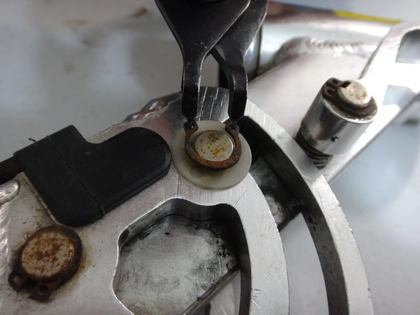
- Remove all six snap rings from the pivoting assembly. The process for using snap ring pliers is shown in Pictures 1-3.
- Hint: Three snap rings are shown in Picture 1. The remaining three are on the other side in the same location.
- Note: It is recomended to wear eye protection during this step since snap rings have a tendency to spring all over the place.
- Remove the black plastic piece indicated in the picture.
- Hint: Use the screwdriver to get under one of the flanges. It should come off very easily.
- Pry the black plastic piece from the front of the scooter. This will take some work, but the piece will come off intact.
- Note: This will allow you to see the inner workings of the pivoting mechanism.
- Remove the spring from the inner workings of the pivoting mechanism with the needle nose piers.
- To remove the spring: First, pull on the visible hook, then push the hook back into the mechanism to remove the tension on the second hook.
- Leave the spring in the mechanism for now. It will be retrieved once the pins are removed.
- Remove all three pins from the pivoting assembly.
- Hint: We found it helpful to use the long bolt from the back wheel to hammer out these pins which were difficult to get out. (Picture 1)
- Note: Once complete, the remaining pieces should fall out as the pivoting piece is removed from the base.
- The teardown is now complete.