Jura Impressa S Model Transformer replacement
ID: 141854
Description: The transformer can break, especially if water...
Steps:
- Always remove the power cord from the wall outlet.
- Lift out the coffee tray
- Remove the lid sealing the coffee bean container
- Remove all of the coffee beans you can possibly remove.
- Pull the adjuster of the coffee bean grinder straight up
- Remove the four T15 Torx screws
- Remove the cup heat plate.
- It can be opened like a book.
- Below the cup heat plate there are three more T15 Torx screws. Remove them.
- The top cover is now free. Lift ´er up and set ´er aside.
- The backpanel is secured with two proprietary screws with oval head. They seem to be rivets, but in fact are screws. The only purpose is, to keep us out of our own devices. You can remove them using an oval drive bit. (Part of some IFixit tool collections or available at a Jura provider or iFixit). In a pitch try needle nose pliers. Here a DIY guide.
- Remove the two oval head screws on the lower edge of the backpanel.
- Lift the panel up.
- Remove the two Torx T15 screws at the bottom of the side panel.
- Remove the Torx T15 screw on the front bottom right.
- Remove the Torx T15 on the right underside of the front access door. Flip the door open a few inches.
- A metal plate rests loosely on the top of the side panel and holds the rotation sensor in place. Note the position of the plate. Simply lift the plate upwards.
- When reassembling, make sure that the sheet metal is put back in exactly the same way.
- First lift the side panel away a little at the bottom, then lift it out at the top.
- Unscrew the Torx T15 screw that holds the control board in place.
- First lift the board a few millimeters up and then a few centimeters out of the machine. Watch out for the many cables.
- Pull the silicone hose off the pump.
- The pump support is like a drawer that can be pulled out to the rear. Two latches hold it in place on the left and right.
- Insert a flat-blade screwdriver into the slots on the left and right and press the latches upward. At the same time, try to pull out the pump support to the rear.
- It may sit a little tightly, but it will come loose.
- Pay attention to the diaphragm regulator when pulling it out. You have to push it up a bit so that the whole pump housing can slide out.
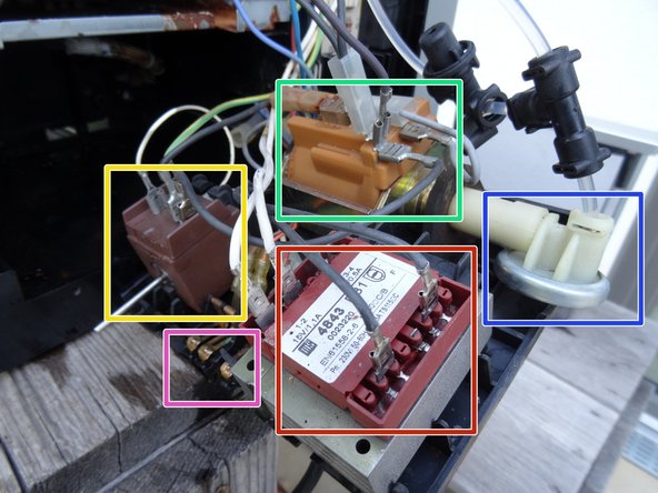
- These components are now easily accessible and can be seen clearly in the second picture:
- Power transformer
- Drip tray sensors
- Pump
- Diaphragm regulator
- Electromagnet for the drain valve
- Disconnect the two gray (230 V) and the two white flat plugs (15 V) from the transformer.
- Lift the transformer out of the pump housing.
- To check the transformer, you can first measure the resistances: at the 15 V terminals (secondary) it should be about 1 ohm, at the 230 V terminals (primary) about 100 ohms.
- You can also apply an AC voltage of about 20 V on the 230 V (primary) side, then you should measure about 1.4 V on the 15 V (secondary) side. Do not swap the primary and secondary sides, otherwise you could get dangerously high voltages.