Sony DualSense Controller Buttons Replacement
ID: 142096
Description: Follow this guide to replace the buttons on a...
Steps:
- Disconnect and power down your controller before you begin.
- Insert an opening pick underneath the middle trim at the bottom-right corner of the controller to release the clips securing it to the case.
- Slide the opening pick along the lower-right edge of the middle trim to release the clips securing it to the case.
- Insert an opening pick underneath the middle trim at the bottom-left corner of the controller to release the clips securing it to the case.
- Slide the opening pick along the lower-left edge of the middle trim to release the clips securing it to the case.
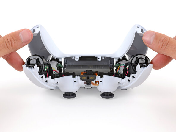
- Use your fingers to lift up the bottom edge of the middle trim to release the remaining clips.
- Lift the middle trim over the joysticks to remove it.
- With one hand, grip the controller and use your thumb to hold down the left trigger.
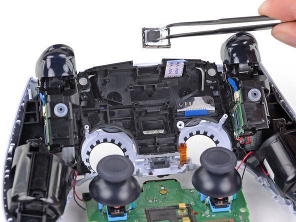
- With your free hand, insert the flat end of a spudger between the L1 and L2 buttons.
- Use the spudger to gently pry the L1 button away from the controller and remove it, holding your finger over the button so it doesn't eject.
- Repeat the previous step to remove the R1 button.
- Use a Phillips screwdriver to remove the two 6.4 mm screws securing the bottom corners of the lower case.
- Use a Phillips screwdriver to remove the two 6.4 mm screws behind the L1 and R1 buttons.
- Be gentle when releasing the rear cover clips—they're delicate and can easily break.
- Use the point of a spudger to release the two clips on either side of the headset jack.
- Tight plastic clips secure the left and right edges of the rear case.
- Insert the flat end of a spudger between the front and rear shells near the bottom of the left edge.
- Slide the spudger along the left edge and gently pry the shells apart to release the clips.
- Repeat the previous step on the right edge to release its clips.
- Lay your controller upside down so the joysticks are on your work surface.
- Hold the controller down with your fingers and use your thumbs to lift the rear case away from the controller to fully separate it.
- Remove the rear case.
- Use a pair of tweezers or your fingers to disconnect the battery from the motherboard.
- Grip the connector, not the wires, when disconnecting.
- Lift the battery straight out of the battery bracket.
- Grab the lower microphone ribbon cable pull tab with your fingers or a pair of tweezers and disconnect it from the motherboard.
- Use a Phillips screwdriver to remove the 6.4 mm screw securing the battery bracket.
- Lift the battery bracket out of the motherboard.
- Grip the right trigger assembly ribbon cable pull tab with a pair of tweezers or your fingers and pull up to disconnect it from the motherboard.
- Do not completely remove the ribbon cable yet.
- Grip the right trigger assembly ribbon cable pull tab with a pair of tweezers or your fingers, and pull up to disconnect it from the trigger assembly.
- Remove the ribbon cable.
- Grip the left trigger assembly ribbon cable pull tab with a pair of tweezers or your fingers and pull up to disconnect it from the motherboard.
- Do not completely remove the ribbon cable yet.
- Grip the left trigger assembly ribbon cable pull tab with a pair of tweezers or your fingers, and pull up to disconnect it from the trigger assembly.
- Remove the ribbon cable.
- Use a pair of tweezers or your fingers to grip the upper microphone ribbon cable pull tab, and pull up to disconnect it from the motherboard.
- Use a pair of tweezers or your fingers to grip the touchpad ribbon cable pull tab, and pull it straight out of the motherboard connector.
- Carefully guide the joysticks through the front case and lift the motherboard out.
- The motherboard is held down by two clips. One between the motherboard itself and the right trigger assembly, and one between the motherboard itself and the left trigger assembly. Gently push on either clip to release the motherboard from its restraints.
- Do not completely remove the motherboard. There are four soldered wires tethering the motherboard to the vibrator motors.
- Use a Phillips screwdriver to remove the two 8.5 mm screws securing the light guide.
- Use a pair of tweezers or your fingers to remove the light guide bracket.
- Use a pair of tweezers or your fingers to remove the light guide.
- Use a pair of tweezers to remove the speaker from the midframe.
- Be sure to reinstall the speaker in the correct orientation with the foam pad on the left side and the gold contact points on the right.
- Use a Phillips screwdriver to remove the two 6.4 mm screws securing the midframe to the front case.
- Carefully lift the midframe and motherboard up and out of the front case.
- Be careful not to strain the vibrator motor wires.
- During reassembly, feed the touchpad's ribbon cable back through its rectangular opening in the midframe.
- Use a pair of tweezers or your fingers to remove the three conductive silicone rubber pads from the inside of the front case.
- The buttons are resting loose in the front case.
- Hold the front case close to the surface of your table and slowly turn the front case over to let the buttons fall out.