Dynex DX-32L151A11 Fuse Replacement
ID: 142230
Description: This guide will be demonstrating the fuse...
Steps:
- Unplug the TV and detach all cables.
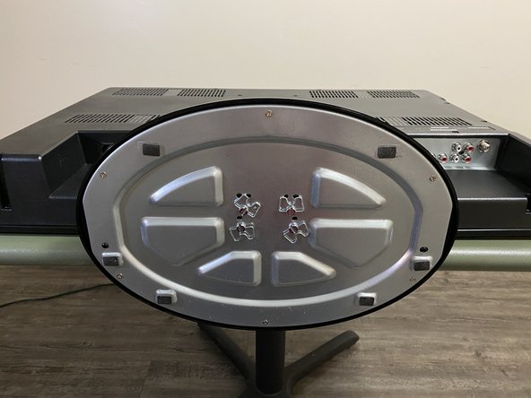
- On a flat surface, carefully lay the TV down with the screen resting on the surface and the stand extending off the edge.
- It is recommended that you place a soft fabric down to ensure the TV is not scratched.
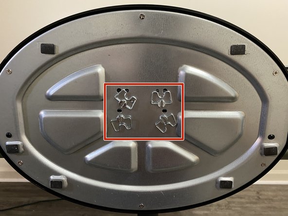
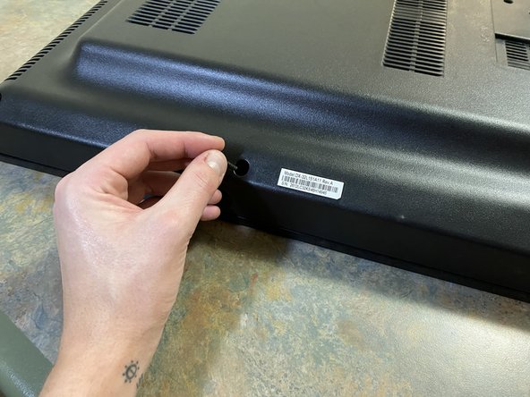
- Locate the 4 screws on the underside of the stand.
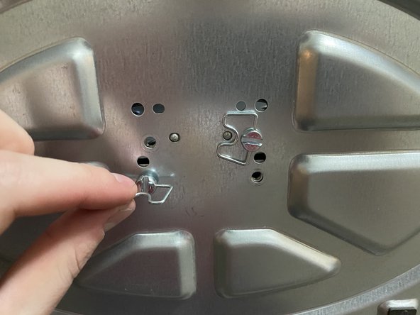
- Loosen and remove the screws using the attached wings.
- Detach the stand from the stand column.
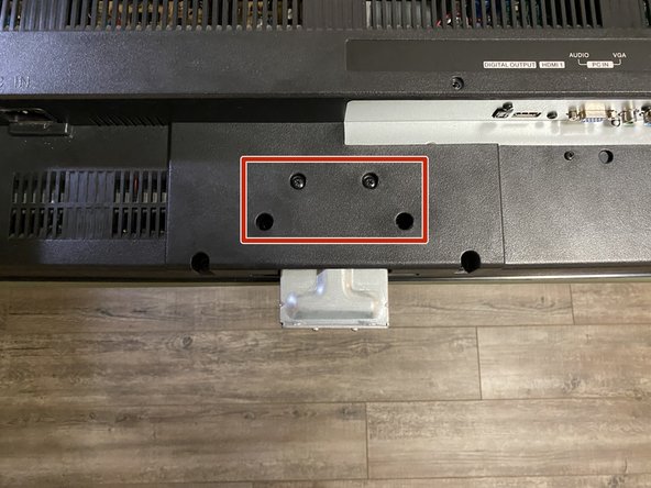
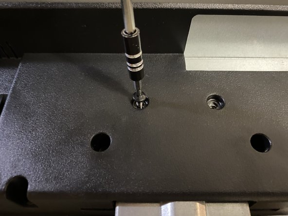
- Locate the 4 screws that attach the stand column to the TV.
- Use the screwdriver to remove the screws.
- Use the tweezers to grab the screws that may be hard to reach.
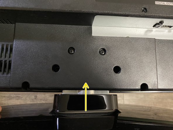
- Once the screws have been removed, pull the stand column out of the TV.
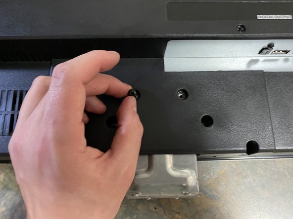
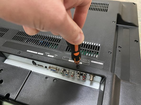
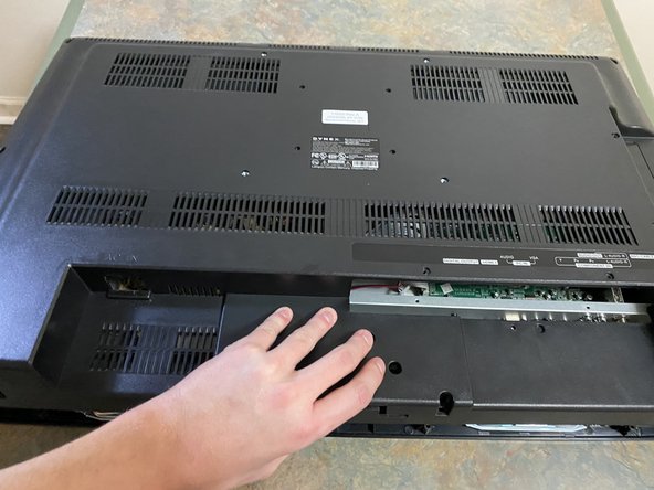
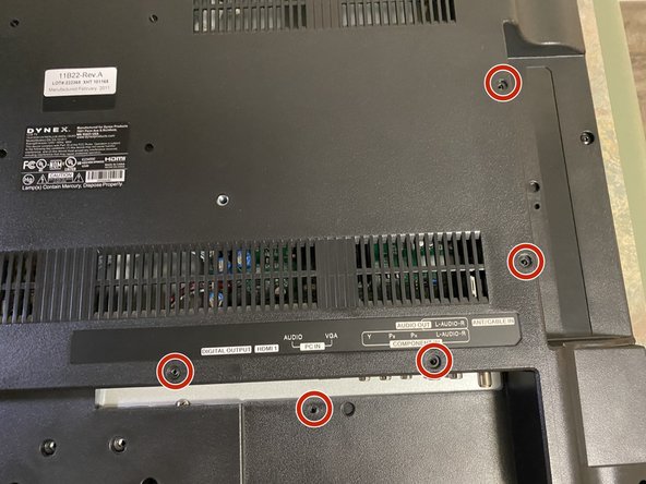
- On the compartments that hold the service port and cable jacks, you will see 5 Input/Output (I/O) screws of a smaller diameter than the others.
- Remove the screws and set them aside.
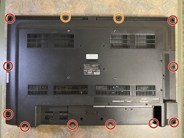
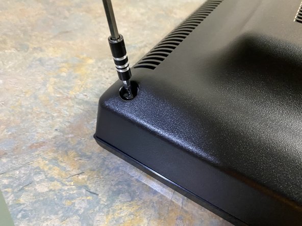
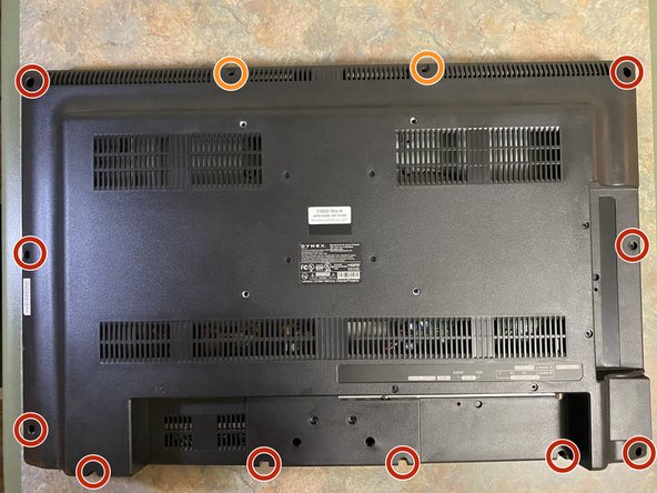
- Unscrew the 10 screws around the perimeter of the TV back cover and use the tweezers to remove them.
- The 2 screws at the top of the TV are a shorter length and should be set apart from the others.
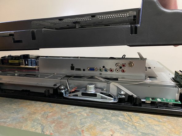
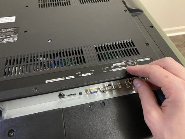
- Carefully lift off the back cover. Also, be sure to take care in removing the back from around the port and jack compartments.
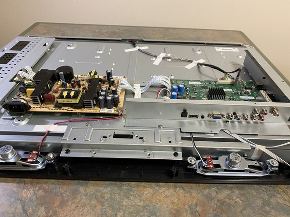
- Make sure that the TV is laying with the bottom closest to you.
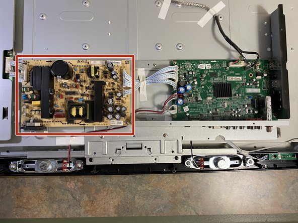
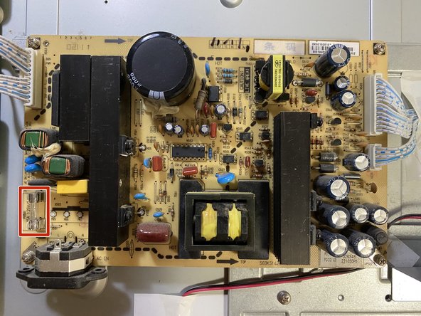
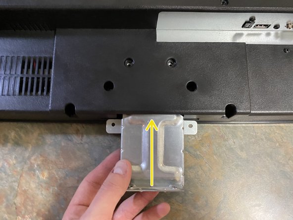
- The PCB that we are interested in should be the yellow device on the left.
- If you are doing this for a different model, the color may not be the same, and they may be in different locations as well. A good way to determine your PCB of focus is to find the PCB that your power ports are saddled or plugged into, rather than your data-related ports like HDMI, audio, etc.
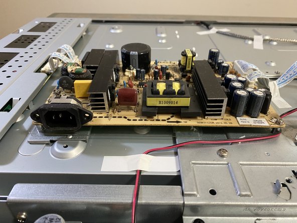
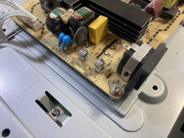
- Looking at the power supply PCB, the fuse should be located down in the bottom left corner next to the power input plug.
- In a different model, the fuse will more than likely be very close to the power input plug.
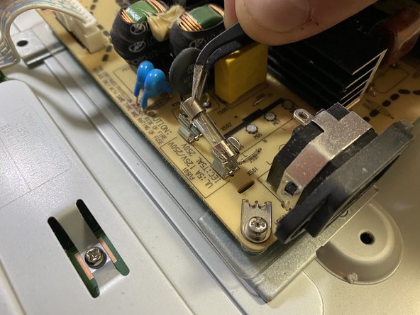
- Use the tweezers to gently lift the fuse out of the snaps that it is saddled in.
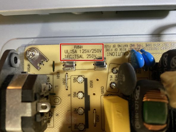
- On our model, it will list the required specifications of the fuse on the PCB (for a different model, it may or may not be listed).
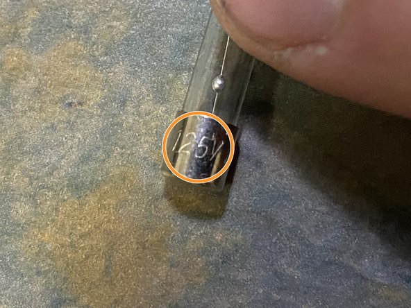
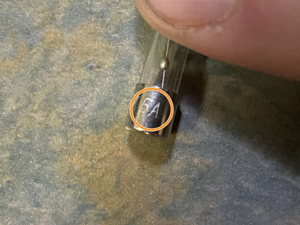
- You can check the specs on the old and new fuse by looking on the end of the cap. It should list the voltage followed by the current.
- The fuse that we need for this model should be rated 125V and 5A. You may see the voltage printed as 125V/250V as well; this is equivalent to a 125V rating.
- This is a very crucial step because if the rating is any lower than its intended design, the fuse will likely break again and you will be fixing this again soon. If the rating is any higher, that is putting the circuit at high risk of greater damage.
- Gently put the new fuse back into its necessary snaps. The direction does not matter.
- Make sure that it is firmly in place and that the snaps are making good metallic contact with the caps of the fuse.
- Carefully replace the plastic cover on the back of the TV, while being certain to maintain proper clearance of the buttons and ports.
- Screw in the 10 longer plastic cover screws.
- Screw in the 2 smaller screws back in the top holes.
- Screw in the 5 smaller I/O screws.
- Gently slide in the stand column until it hits the end of the slot.
- Screw in the 4 screws that are associated with the stand column.
- Gently slide on the base and reattach the screws until it is snug.