HTC Vive Lens and OLED Assembly Replacement
ID: 142454
Description: This guide will show you how to replace the HTC...
Steps:
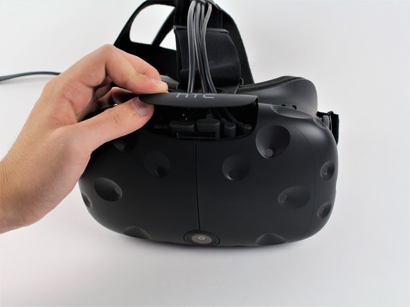
- Slide the HTC panel covering the cables forward, away from the Vive.
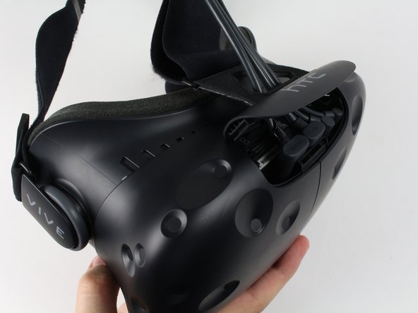
- Gently pull on each of the four connectors to remove the sound and Three-in-One cables.
- Undo the hook and loop tape on the straps.
- Slide the ends of the straps through the hinge loops.
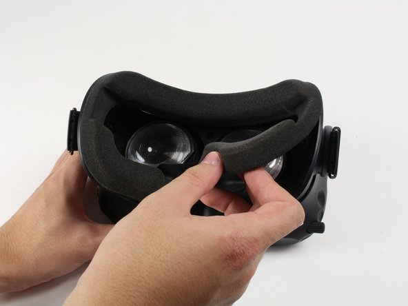
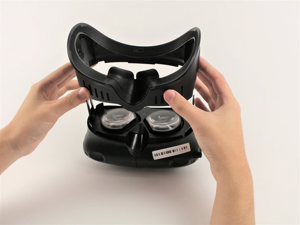
- Pull the facerest cushion off away from the Vive, separating the hook and loop tape.
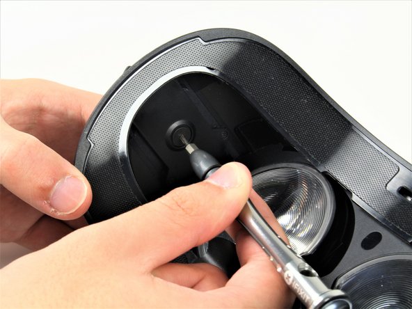
- Use a T6 Torx Screwdriver to remove either of the two 12mm hinge screws holding the two hinges in place.
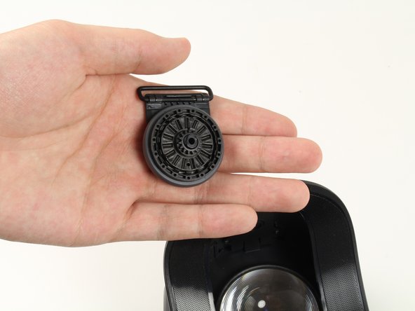
- Allow the hinge to fall away once the screw is removed.
- Repeat for the opposite side.
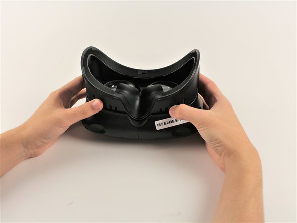
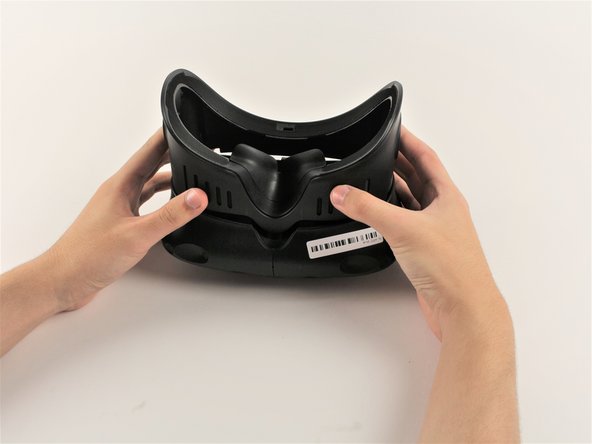
- Slide the plastic facerest away from the device.
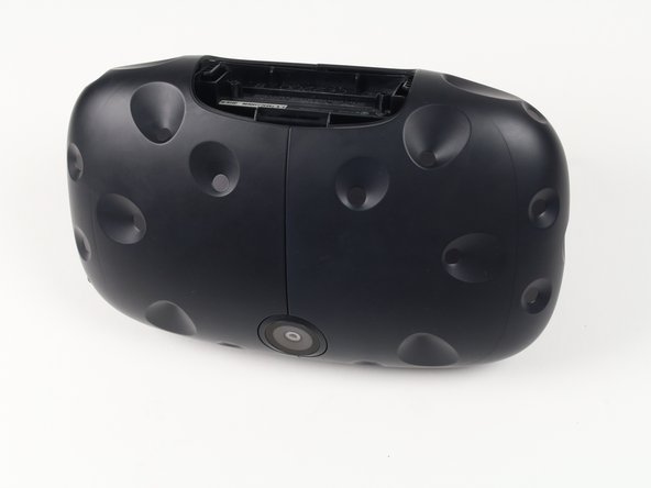
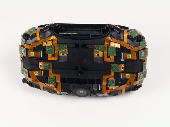
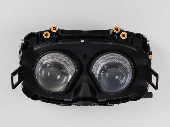
- Orient the Vive so that the camera is facing towards you and the connector ports are facing upwards.
- There are four screws you need to remove that are covered with small black stickers (two on top, two on bottom).
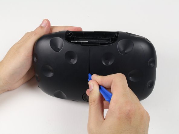
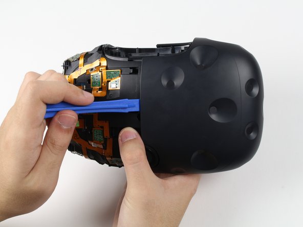
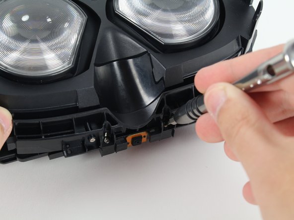
- Use a plastic opening tool to gently pry up the left side of the outer sheath.
- If the left sheath is glued down, slide your plastic opening tool along the middle seam to break the bond.
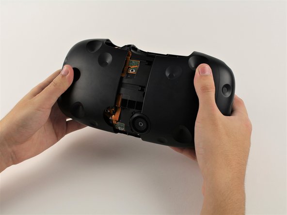
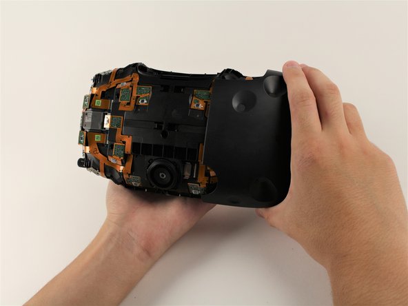
- Slide the left side of the sheath outwards.
- Slide a plastic opening tool underneath the right side of the sheath to remove any remaining glue.
- Using the plastic opening tool, pry the right side of the sheath upwards slightly.
- Using your hands, slide the right side of the sheath outwards.
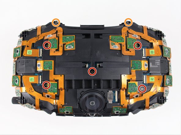
- Remove the five 4mm Philips #00 screws holding the sensor array to the motherboard.
- Remove the two 4mm Philips #00 screws holding the sensor array to the midframe.
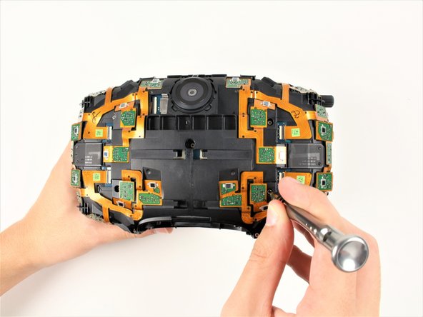
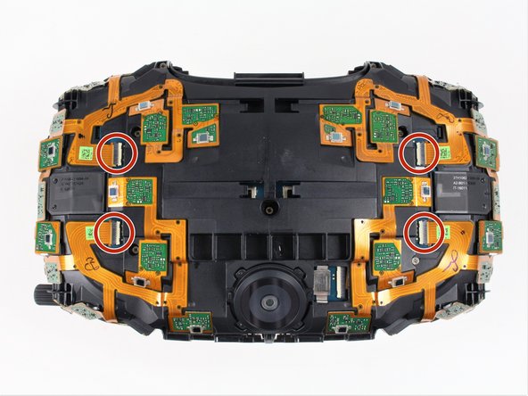
- Using a pair of ESD safe tweezers, gently pull the four ribbon cables out horizontally from the sensor array.
- Be careful not to lift the sensor array too far from the rest of the device because the camera ribbon cable may tear.
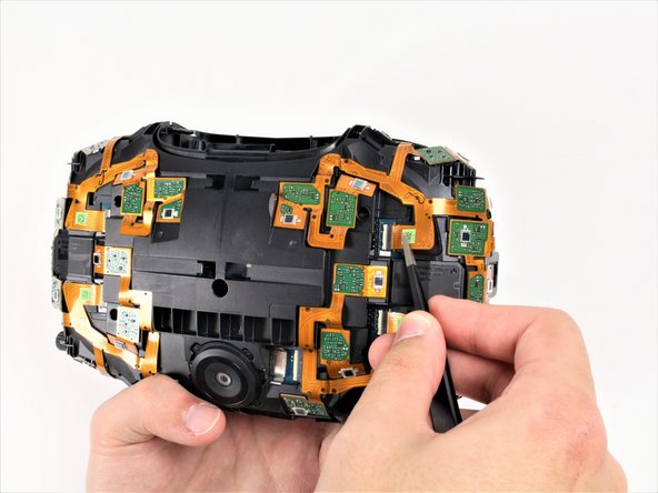
- Lift the sensor array away from the rest of the Vive until the camera cable tugs back and hold it in place.
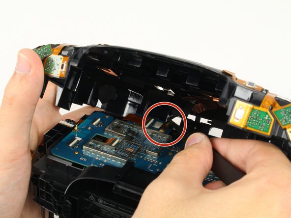
- The camera ribbon cable must be pulled out of its socket vertically, as opposed to all other ribbon cables which slide out horizontally.
- Disconnect the camera by lifting its ribbon cable up and away from the motherboard using a pair of ESD safe tweezers.
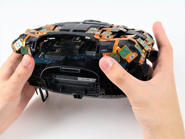
- Lift the sensor array upwards away from the motherboard to separate the array from the device fully.
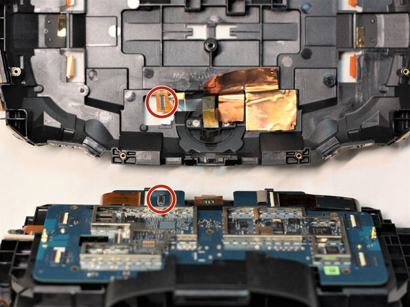
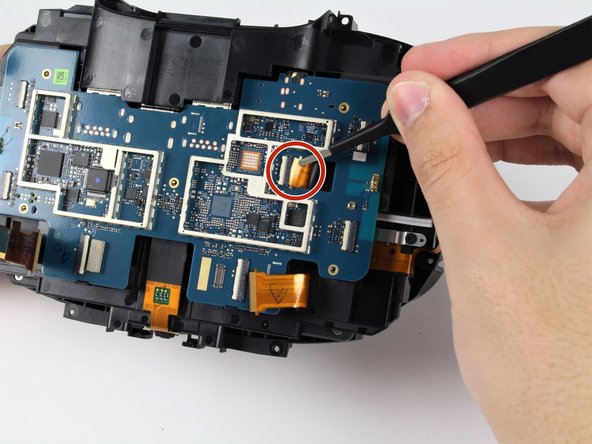
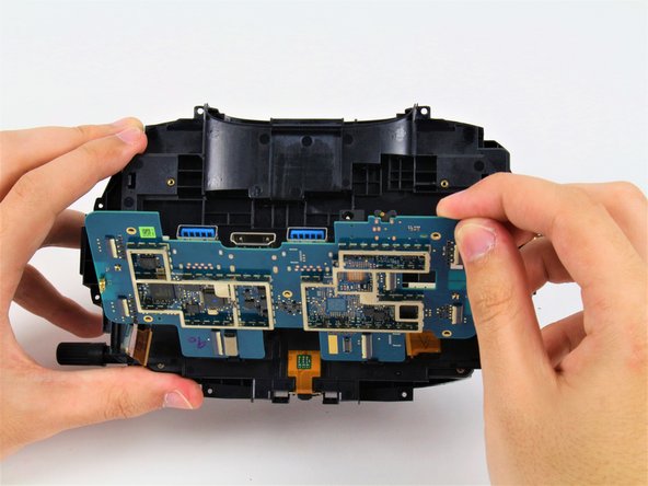
- Loosen the three ribbon cables that are attached to the motherboard by grabbing the tabs on the side of the ribbon cables' connectors and pulling gently outwards.
- Fully detach the same three ribbon cables by grabbing each cable with tweezers and sliding them outwards horizontally.
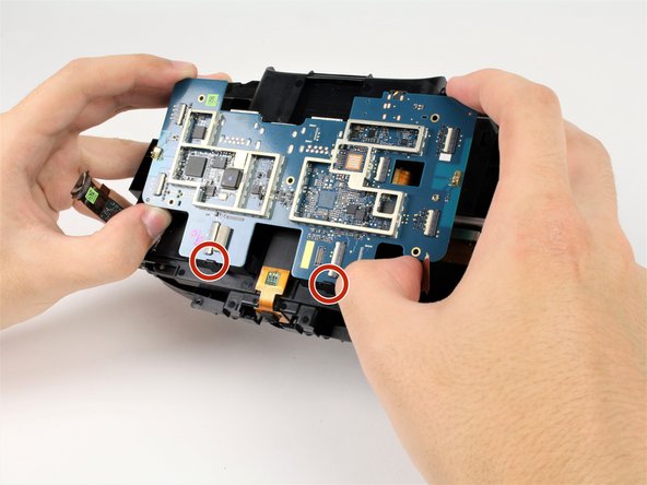
- The bottom of the motherboard is secured by two hooks, indicated in the first photo. Do not pull the motherboard directly outwards, as doing so can cause damage.
- Pivot the top of the motherboard outwards until it has cleared the top of the plastic housing.
- Pull the motherboard up and away from the plastic housing, away from the two hooks.
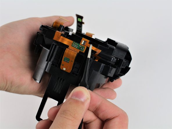
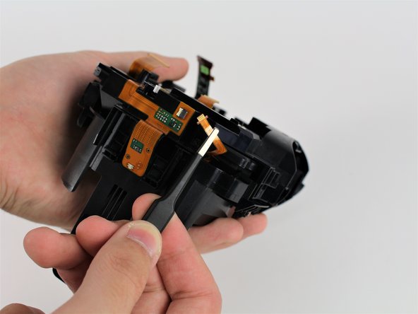
- Grab the tabs on the side of the ribbon cable's connector and pull gently outwards to loosen it.
- Remove the ribbon cable for the power button by grabbing the cable with tweezers and sliding it outwards horizontally.
- The ribbon cable for the power button is located on the side of the device opposite from the focus knob.
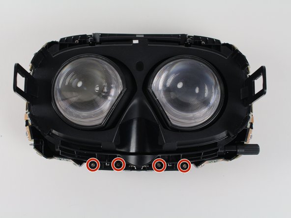
- Remove the four 4mm #00 Philips screws by the nose rest holding the midframe to the eyepiece assembly.
- Remove the four 4mm #00 Philips screws on the top of the device, directly across from the four by the nose.
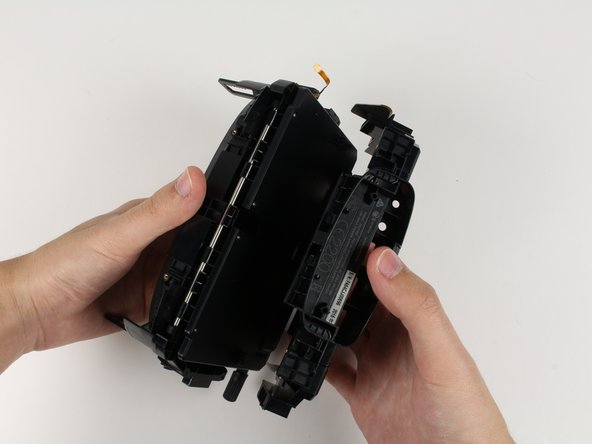
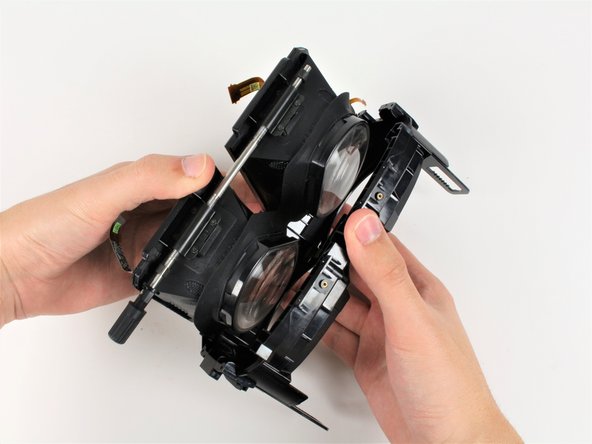
- With one hand on the midframe and the other on the eyepiece assembly, pull the two parts away from each other.
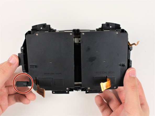
- Pivot the bottom rod attached to the eyepieces outwards from the facerest to free the eyepieces.
- The bottom rod is the rod that the focus knob is attached to.
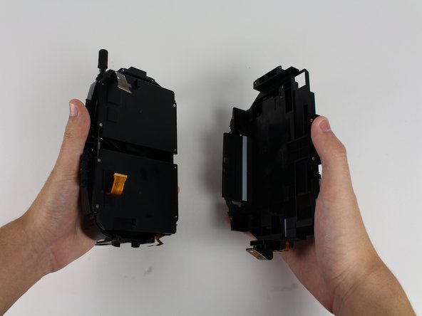
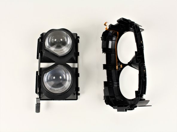
- Pull facerest from the eyepieces to separate the parts.
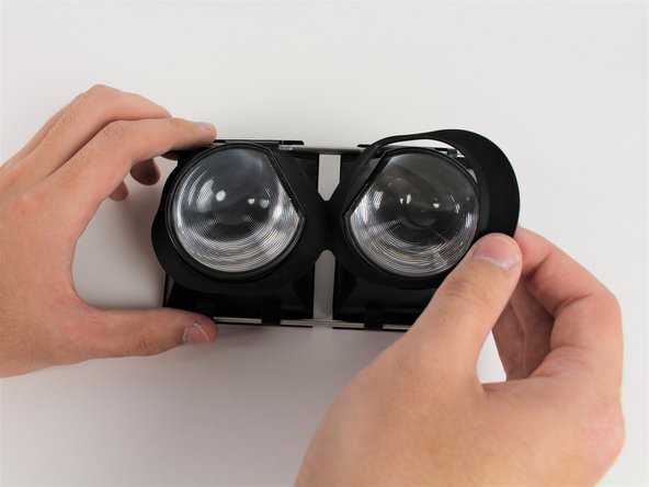
- Pull off the rubber liner between both eyepieces.
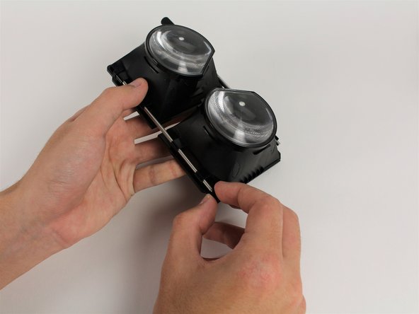
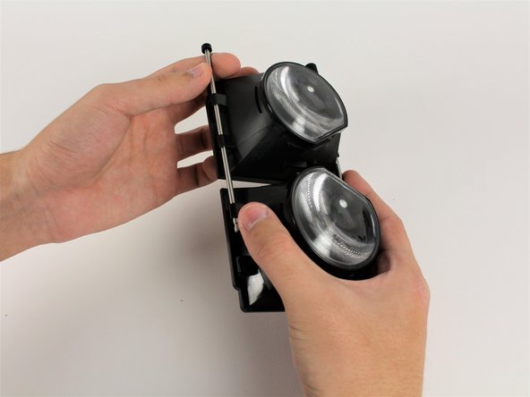
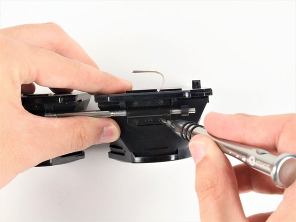
- Pull one of the rubber ends off the top rod.
- The top rod is the rod that does not have the focus knob attached to it.
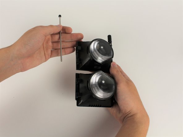
- Pulling from the other end of the rod, slide the top rod out.
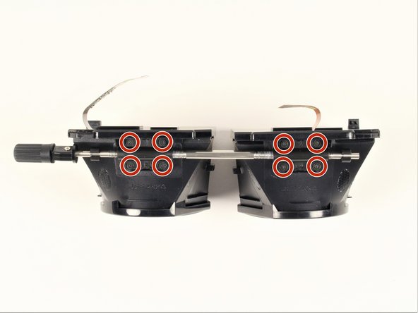
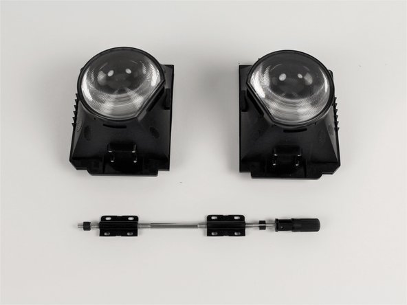
- Remove the four 3mm #00 Philips screws from each eyepiece, removing eight screws total.
- The eyepieces will detach from the bottom rod once the screws are removed.