MacBook Pro 13" Two Thunderbolt Ports 2020 Touchbar Replacement
ID: 142585
Description: Use this guide to replace a touchbar on an...
Steps:
- To begin, we will need to remove 6 total screws
- 2x 6.9mm Pentalobe P5
- 2x 5.5mm Pentalobe P5
- 2x 3.5mm Pentalobe P5
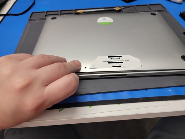
- After the screws are removed, grab a suction cup. We used iFixit's Heavy Duty Suction cup.
- Place the suction cup towards the bottom of the Macbook
- Pull up on the suction cup; Creating about 0.15in worth of space from the panel and the Macbook.
- Don't lift it any higher, as it could damage inside compenents
- While creating the gap between the Macbook and the back panel, insert an opening pick into the gap about 0.2in.
- Don't insert the pick further, as this could cause internal damage
- Move the pick towards the left side of the Macbook and around the corner edge.
- Bring the pick up towards the top of the Macbook
- Once you reach about the middle of the Macbook, you should hear a click. This is good! You have now unhooked part of the back panel.
- Repeat Step 3 but on the right side of the Macbook
- Once done, don't remove the back panel just yet. It is still attached to the Macbook
- Insert your fingers in-between the back panel and Macbook and pry upwards to unhook the middle hook keeping the back panel connected to the Macbook
- Don't attempt to remove the back panel yet. It is still connected to the Macbook
- Grip the back panel with one hand
- Grip the Macbook with the other hand
- And pull the left side of the back panel AWAY from the HINGE side of the Macbook
- This will require a lot of force. Don't be afraid to pull hard while keeping the Macbook steady and in position.
- Repeat this with the right side of the Macbook
- Once pulled from the hinge area, you may now remove the back panel and place it out of the way.
- Locate the battery connector cover
- Take a pair of tweezers and gently remove the plastic cover from the Logic Board
- Be careful not to pull on any flex cables
- Locate the small flex cable covering the battery terminal
- Take a pair of tweezers in one hand and pull up on the plastic flap
- Take the hook end of a Halberd Spudger in the other hand and gently pry up the retaining flap on the battery cable ZIF socket
- Be sure you are prying up on the hinged retaining flap, not the socket itself.
- Make sure to use gentle force as this shouldn't require a lot of force. If excessive force is used, you could break the flex cable.
- Take your tweezers and pull on the plastic cover away from the ZIF socket to remove the flex cable from its socket
- Make sure to use gentle force as this shouldn't require a lot of force. If excessive force is used, you could break the flex cable.
- Remove the 3.8mm Torx T5 screw from the battery connector
- Take the flat end of a spudger and pry up the battery connector to a 90° angle
- Prying it this far away from the contact pads ensures there won't be any contact between the Logic Board and the battery
- Be mindful of the battery connector. If you flip the Macbook and lay it down on the table, you could damage the battery connector
- Locate the left hinge cover
- Remove 2x 2mm Torx T3 screws securing the hinge cover to the Macbook
- Take a pair of tweezers and remove the hinge cover
- Locate the right hinge cover
- Remove 2x 2mm Torx T3 screws securing the hinge cover to the Macbook
- Take a pair of tweezers and remove the hinge cover
- Locate your LCD flex cable towards the top of the Macbook
- Locate the bottom cover plate
- Remove 2x 3.2mm Torx T3 screws securing the bottom cover plate to the MacBook
- Take a pair of tweezers and remove the brackets
- Locate the top cover plate of the LCD flex cable
- Remove 2x 1.8mm Torx T3 screws securing the top cover plate to the Macbook
- Take a pair of tweezers and remove the now free cover plate
- Take the flat end of a spudger and gently pry up the LCD flex cable from its port
- Make sure not to pry the socket itself
- Lift LCD flex cable up and away from the Macbook
- Locate the left LCD screen spring
- Remove 2x 4.1mm Torx T3 screws securing the spring to the MacBook
- Locate the right LCD screen spring
- Remove 2x 4.1mm Torx T3 screws securing the spring to the MacBook
- Locate antenna connector cover
- Take a pair of tweezers and gently pry up the cover from the Logic Board
- Be careful not to pry anything but the plastic cover
- Remove 1x 3.9mm Torx T5 screw securing the antenna cables to the MacBook
- Take the flat end of a spudger and gently pry up the antenna cables from their sockets
- Be careful not to pry up the socket itself
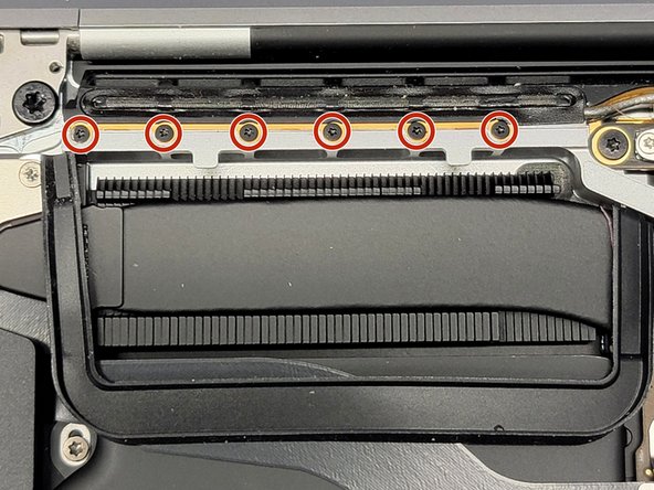
- Locate the antenna towards the top of the Macbook
- Remove 12x 1.2mm Pentalobe P2 screws securing the antenna to the MacBook
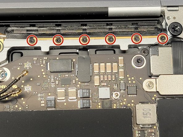
- Locate the LCD board towards the top of the Macbook
- Remove 4x 3.4mm Torx T5 screws securing the LCD board to the MacBook and to the antenna
- You should now be able to remove the antenna from the Macbook.
- Gently pry & pull away the antenna cable from the Macbook while routing it's cable through their hole. Take care here, as the antenna sockets can be ripped from the board easily.
- You can straighten out the cables to make it easier or simply twist and turn the antenna to maneuver the cables out of their hole.
- Locate the left LCD screen hinge
- Remove 2x 4.5mm Torx T9 screws that secure the hinge to the MacBook
- Leave 1 screw to make removing the LCD screen easier
- Locate the right LCD screen hinge
- Remove 2x 4.5mm Torx T9 screws that secure the hinge to the MacBook
- Leave 1 screw to make removing the LCD screen easier
- Place MacBook at the edge of your work bench and let the screen overhang
- Locate and remove the remaining 2x 4.5mm Torx T9 screws securing the 2 hinges to the MacBook
- The MacBook display will now freely dangle on the edge of the table. It won't fall due to the hinges being inside a divot in the MacBook
- Bend the LCD screen slightly towards you
- Gently pry up the LCD screen from the Macbook, while guiding the hinges out of their divots
- During reassembly make sure to place the hinges into the divots. Once in the divots, you can then screw 1 screw back into each hinge and then shut the Macbook. This will allow you to properly arrange and align the LCD hinges
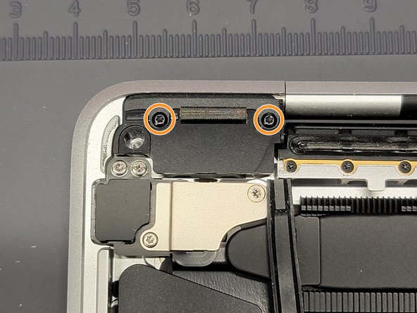
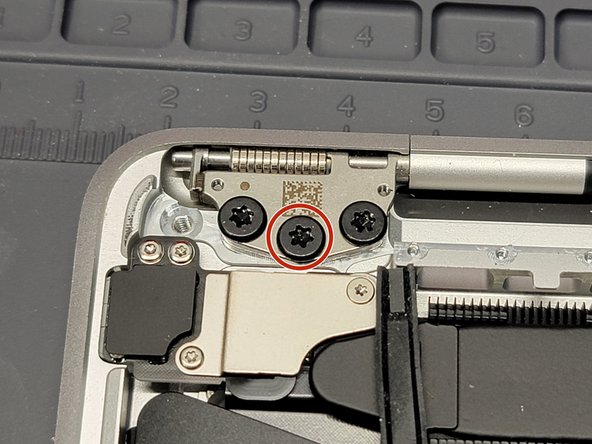
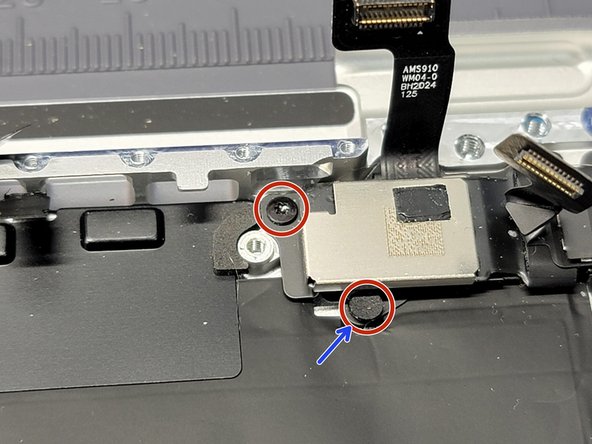
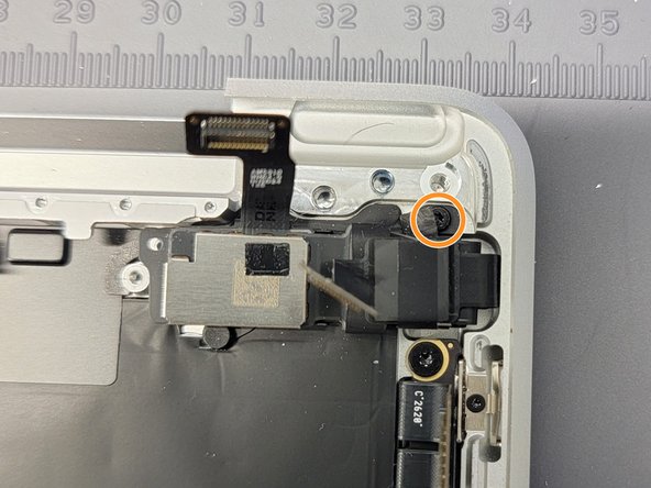
- Locate the power button flex cable bracket towards the top left of the MacBook
- Remove 2x screws securing the bracket to the MacBook
- 1x 5mm Torx T3 Screw
- 1x 1.4mm Torx T3 Screw
- During Reassembly: You may want to use this screw to screw in the logicboard standoff underneath.
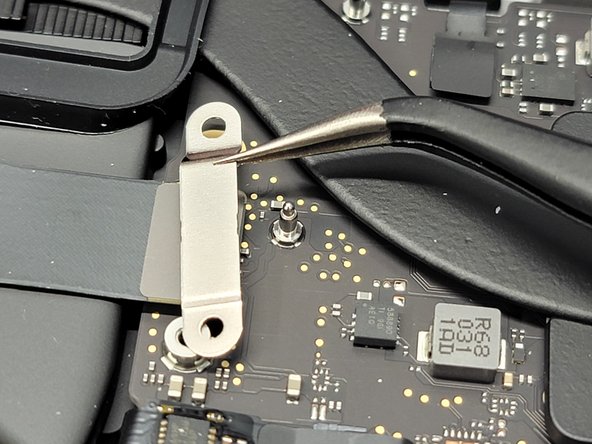
- Take a pair of tweezers and remove the bracket
- Make sure to grab and pickup ONLY the bracket.
- Locate the trackpad's flex cable bracket towards the middle of the Macbook
- Remove 2x 1.9mm Torx T5 screws securing the bracket to the Macbook
- Then take a pair of tweezers and remove the bracket
- Make sure to grab and pickup ONLY the bracket.
- Using the flat end of a spudger gently lift the connector from its socket
- Make sure to not pry the socket itself
- It might make it easier if you pry it up a little on all 3 sides
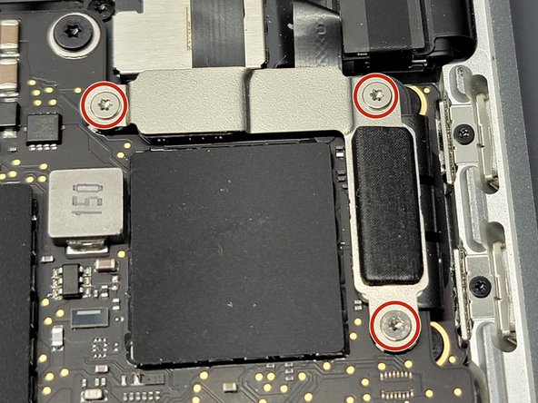
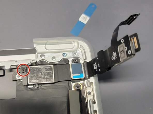
- Locate the right speaker flex cable bracket
- Remove 2x screws securing the bracket down to the Logic Board
- 1x 3.7mm Torx T5
- 1x 2.6mm Torx T5
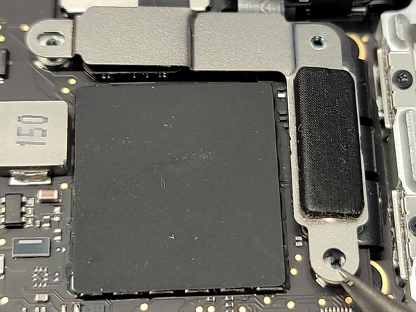
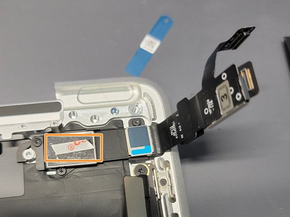
- Take a pair of tweezers and remove the bracket
- Make sure to not grab the flex cable while removing the bracket
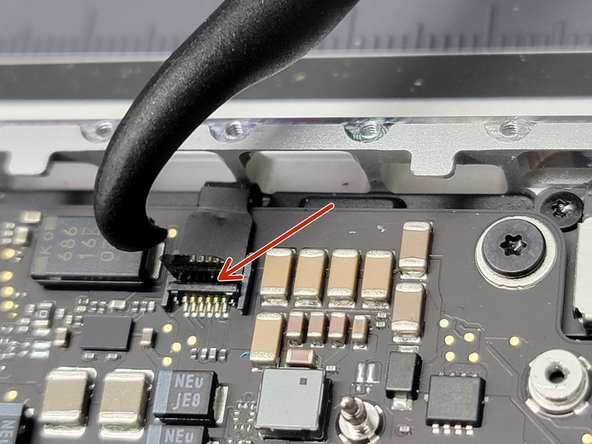
- Take the flat end of a spudger and carefully pry up the flex cable from its socket
- Be careful not to pry up on the socket itself
- There are sensitive filters near the socket. Make sure to be ultra careful not to knock one of those "microscopic" filters off.
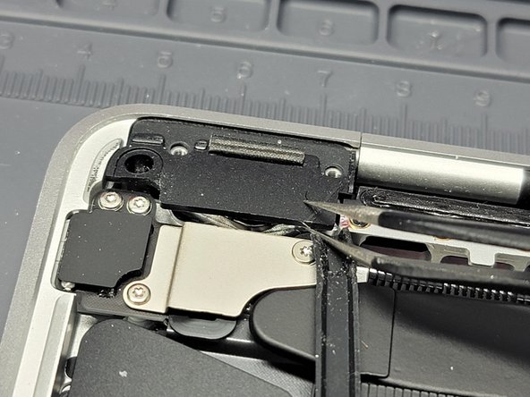
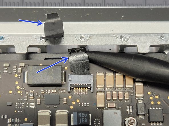
- Locate the left speaker and touch bar bracket
- Remove 3x 1.4mm Torx T3 screws from the bracket
- Take a pair of tweezers and remove the bracket
- Be sure not to grab any of the flex cables while removing the bracket
- Take the flat-end of a spudger and gently pry up all 3 flex cables from their sockets
- Be careful not to pry up on the socket itself
- There are sensitive filters near the socket. Make sure to be ultra careful not to knock one of those "microscopic" filters off.
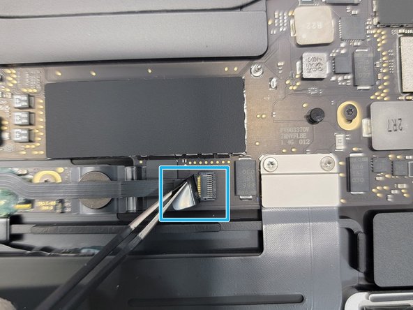
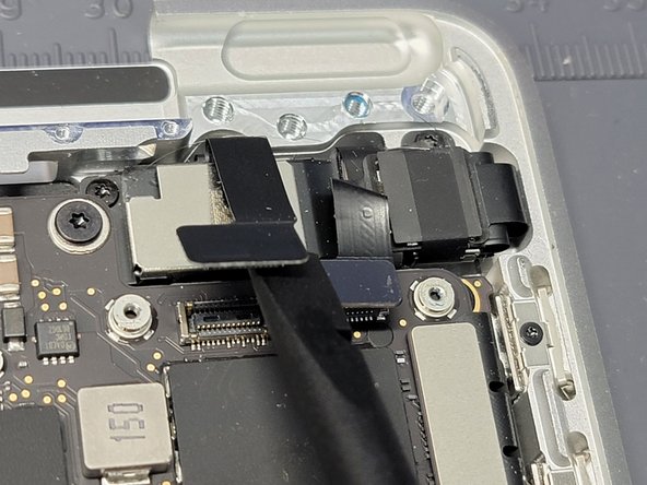
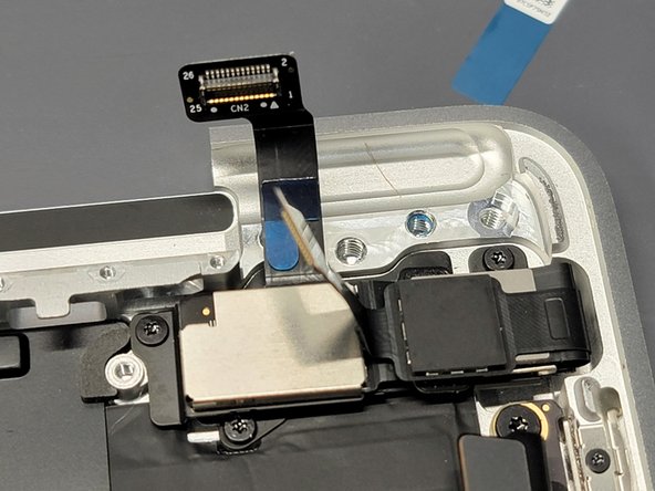
- Locate 8x flex cables connected the logic board
- For each flex cable, pull up on their plastic flap with a pair of tweezers
- Take the hook end of a Halberd Spudger and gently pry up the retaining flap on the ZIF socket of each cable
- Make sure to use gentle force as this shouldn't require a lot of force. If excessive force is used, you could break the flex cable.
- Be sure you are prying up on the hinged retaining flap, not the socket itself.
- Take your tweezers and pull on the plastic cover to pull each cable away from the ZIF socket to remove the flex cable from it's socket
- Make sure to use gentle force as this shouldn't require a lot of force. If excessive force is used, you could break the flex cable.
- If any of the plastic flaps break off don't worry! You can use a combination of your spudger and tweezers to gently pull out the flex cable from it's respective socket
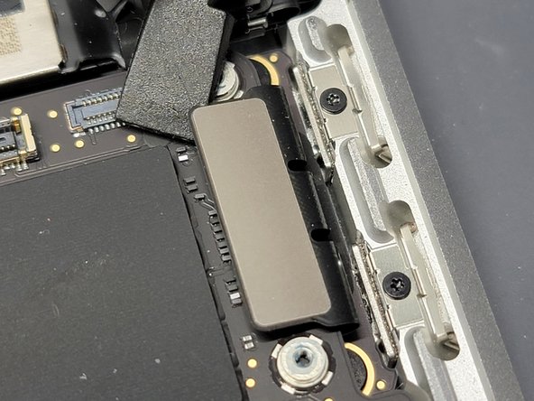
- Locate and remove 5x Logic Board Screws
- 3x 3.4mm Torx T5 screws
- 1x 3.6mm Torx T5 stepped screw
- 1x 3.3mm hex standoff (3mm drive)
- During Reassembly: It may be difficult to screw the top left logic board standoff back in. If you are finding it hard to do this, take the 1.4mm screw that we removed to remove the power button bracket and screw it into the top left logic board standoff. Afterwards, take the now "cyborg" screw and screw it into the logic board.
- Don't forget to remove the 1.4mm screw from the logic board standoff during reassembly
- Take the hook end of your Halberd Spudger and gently pry up the top left corner of the logic board
- Now remove the logic board from the Macbook
- Be careful not to rip or tear any flex cables while removing or placing down the logic board
- During reassembly, make sure to take your spudger while placing the logic board down and move any flex cable away from being squashed, tore, or ripped.
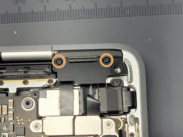
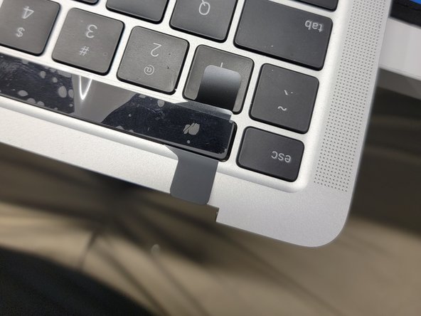
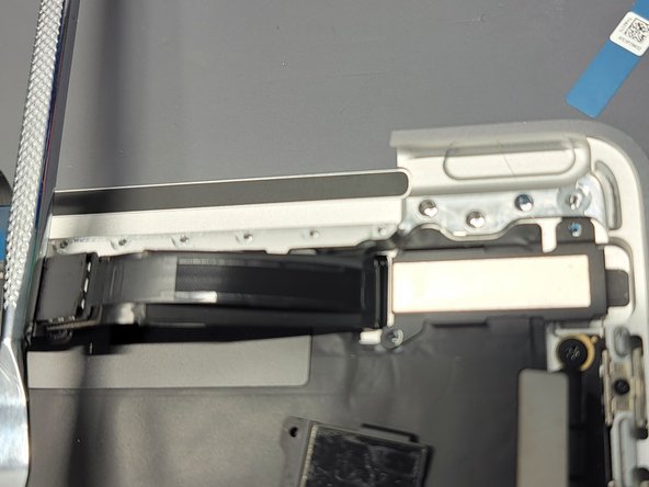
- Locate the touchbar flex cable mess towards the top right of the Macbook
- You will be removing a total of 3 screws to release this cabled mess from the frame
- 2x 2.4mm
- One of these are "hidden" by a small pad. Take a pair of tweezers and remove this pad to access the screw head
- 1x 1.7mm
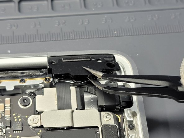
- These brackets that keep the cabled mess down and attached to the frame are adhered to the cabling
- Remove these brackets from the flex cabling mess
- TIP: Be mindful of how the brackets are positioned in relation to the cables and frame. Take pictures to reference. Without these brackets, the cables will be free inside the frame (which is not good).
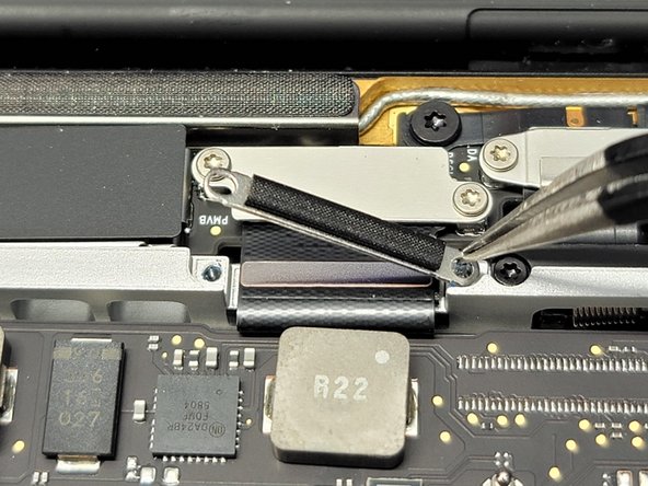
- There are also little wraps of plastic holding different parts of the cabling together. Go ahead and CAREFULLY remove these as we won't need them during reassembly and we do need them removed to completely remove the touchbar
- Follow this guide to properly install the new touchbar
- There are 2 methods that we can take towards removing this annoying touchbar. We went ahead and performed what we thing is the harder method.
- Method 1: Take 2 tweezers or handles and wrap very thin wire around them. Then pull the wire underneath the touchbar LCD gently while being careful not to damage the keyboard
- This method keeps the frame underneath the touchbar from scratching a whole bunch, eliminates the possibility of the keyboard keys "melting" from the Adhesive Remover, and allows you to possibly reuse the touchbar.
- Method 2: What we did. Remove the touchbar digitizer first by prying it up and off the touchbar LCD. Then use a combination Adhesive Remover and a Technician's Razor Set to remove the touchbar LCD.
- This method takes longer and more patience. However, we didn't have wire at our disposal and we weren't needing to reuse the touchbar
- Take a Halberd Spudger and insert the knife end right underneath the plastic of the digitizer
- Run the Halberd Spudger along the edge of the touchbar digitizer
- The digitizer should separate surprisingly easy.
- Feed the Touchbar digitizer cable through the hole and remove the digitizer
- Take a technician's knife and start prying away the LCD of the touchbar.
- Use adhesive remover from time to time to help loosen the adhesive
- Don't let any of the adhesive remover touch the keyboard keys or any plastic for that matter. It will melt and eat away at any plastic it comes in-contact with
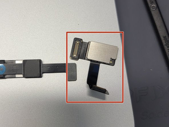
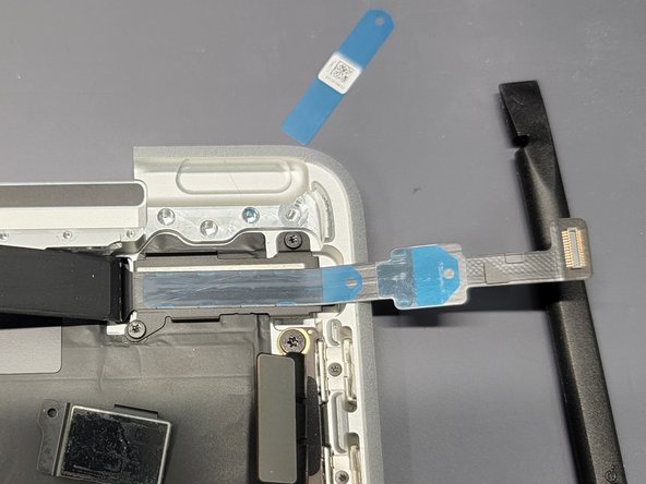
- Locate the cable side of the NEW touchbar
- The touchbar is very sensitive and can break easily. Make sure to handle with care while maneuvering it around.
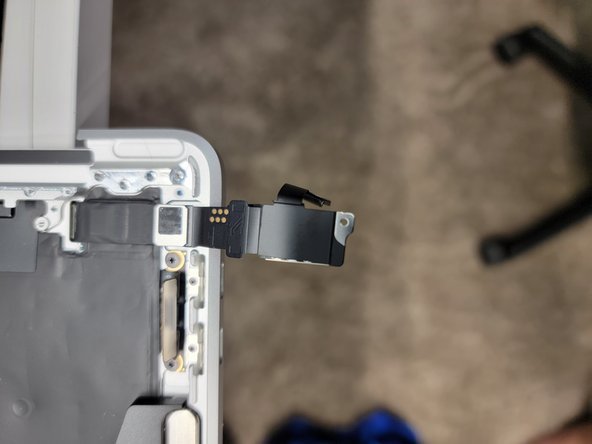
- Locate the detachable end of the flex cable and use the flat-end of a spudger to disconnect the larger portion.
- Be aware of how the end portion is oriented in relation to the smaller cable. When reattaching this part, it is important to place it correctly back into it's socket and not backwards.'''
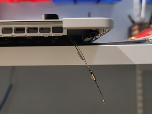
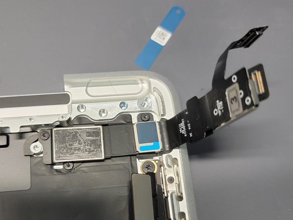
- Locate the little hole near the left side of the Macbook and feed the touchbar flex cables through it.
- DON'T remove any plastic off the touchbar just yet. The adhesive attached to the touchbar is VERY strong and you will only have 1 chance to place the touchbar down correctly.
- After feeding the flex cable through th hole, reattach the bigger portion of the touchbar flex cable
- Make sure to reattach this part correctly as if you don't, it can cause damage to the cable.
- Locate the larger bracket and place it down in it's spot. Reference the images for assistance.
- Might make it easier to perform the below steps if you screw the bracket down into place. Reference step 36 for screw placement
- Place something heavy enough to keep the flex cables back but light enough not to damage them (Ex: metal spudger)
- Remove the blue adhesive protector from the touchbar digitizer cable
- Align cable to bracket and press the flex cable firmly down onto the bracket
- Don't remove the blue adhesive protector on the other side of the flex cable just yet
- Remove both blue adhesive protectors
- Take touchbar LCD flex cable and place it against the touchbar digitizer flex cable
- Press firmly on the flex cables to adhere the 2 together
- Locate the second bracket and place it in it's correct spot. Reference the photos and step 36 for assistance.
- Screw down the bracket using it's screw. Reference step 36.
- Place a small strip of adhesive to the bracket. We used basic Tesa tape
- Remove the white protective top of the tesa tape
- Remove the blue protective film on the flex cable
- Take the flex cables and bring them down to the bracket
- Press the flex cables firmly onto the bracket to adhere the flex cables to the new bracket
- Carefully lift the touchbar assembly up and out of it's little crevice
- Remove the black adhesive protector from the touchbar
- Carefully align the touchbar to it's crevice
- Once perfectly aligned, place the touchbar into it's crevice and push firmly but not hard on the touchbar to finalize it.
- You may only have one shot at aligning the touchbar properly once the adhesive touches the Macbook. So be careful, precise and don't rush it.
- Once this is done, follow this guide backwards starting with Step 35 to reassemble the Macbook