MacBook Air 13" Early 2020 Logic Board Replacement
ID: 142677
Description: Use this guide to replace the logic board in an...
Steps:
- Before starting this procedure, you should disable your Mac's Auto Boot feature. Auto Boot powers on your Mac when you open the lid, and may be accidentally triggered during disassembly. Use this guide to disable Auto Boot.
- If your MacBook is running Big Sur v11.1 or later, disabling Auto Boot may not work. You can proceed normally, but make sure to disconnect the battery as soon as you're inside.
- Completely power off and unplug your MacBook Air before you start. Close the display and flip the entire laptop upside-down.
- Use a P5 driver to remove the following screws:
- Two 7.9 mm screws
- Two 7.1 mm screws
- Six 2.6 mm screws
- Throughout this repair, keep track of each screw and make sure it goes back exactly where it came from to avoid damaging your MacBook.
- Wedge your fingers between the display and the lower case and pull upward to pop the lower case off the Air.
- Remove the lower case.
- To reinstall the lower case:
- Set it in place and press firmly to engage the two hidden clips underneath. You should feel and hear them snap into place.
- Peel back the tape covering the battery connector enough to reveal the connector underneath.
- Use a spudger to slide the battery connector parallel to the logic board and out of its socket on the logic board.
- Use a T4 Torx driver to remove the two 1.4 mm screws securing the trackpad cable cover.
- Remove the trackpad cable cover.
- Use the flat end of a spudger to pry the trackpad cable connector up and out of its socket.
- To re-attach press connectors like this one, carefully align and press down on one side until it clicks into place, then repeat on the other side. Do not press down on the middle. If the connector is misaligned, the pins can bend, causing permanent damage.
- The left speaker will be on your righthand side when working on the MacBook, as it's laying upside down.
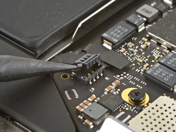
- Slide the pointed end of a spudger underneath the left speaker cable and pry straight up to disconnect it from the logic board.
- With the connector disconnected, slide the flat end of a spudger under the cable to separate the adhesive securing the cable to the logic board.
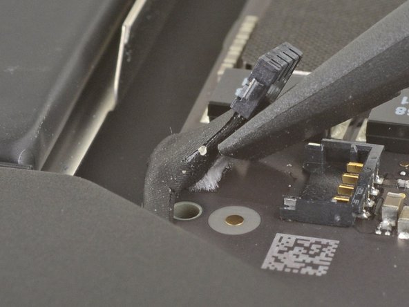
- Use a pair of tweezers to peel back any tape covering the microphone cable connector.
- Use the pointed end of a spudger to lift up the small locking flap on the microphone cable's ZIF connector.
- Slide the microphone cable out of its connector.
- If possible, grip the cable by the tape, not by the cable itself.
- Use a T4 Torx driver to remove the two 1.4 mm screws securing the USB-C connector cover.
- Remove the USB-C connector cover.
- Use the flat end of a spudger to pry the USB-C cable connector up and out of its socket on the logic board.
- Use a spudger to lift up the small locking flap on the sound board cable's ZIF connector.
- Slide the sound board cable out of the ZIF connector.
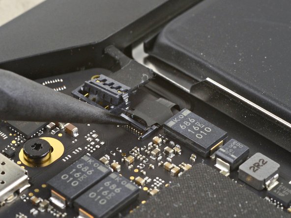
- Peel back the black tape covering the fan cable connector.
- Use the tip of a spudger to lift up the locking flap on the fan cable's ZIF connector.
- Slide the fan cable out of the ZIF connector.
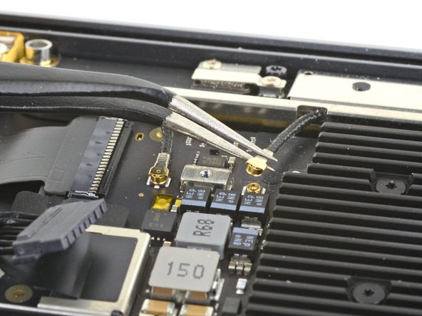
- Use a T4 Torx driver to remove the 1.4 mm screw securing the antenna cable cover.
- Remove the antenna cable cover.
- Use a pair of tweezers to grip the antenna connector close to its base.
- Pull straight up to disconnect the cable.
- Repeat for the second antenna cable.
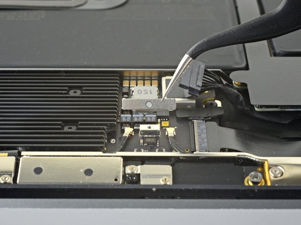
- Use a T4 Torx driver to remove the two 1.5 mm screws securing the display cable connector cover.
- Remove the display cable connector cover.
- Use the flat end of a spudger to pry the display cable connector straight off of the antenna board to disconnect it.
- Use a T5 Torx driver to remove the six screws securing the logic board to the upper case:
- Three 3.5 mm screws
- One 5.8 mm cushioned screw
- Two 2.0 mm screws
- Remove the logic board.
- When you reinstall the logic board assembly, verify that no cables get trapped under the board as you lower it into place. Check each of the seven locations carefully:
- Battery cable
- Fan cable
- Audio board cable
- USB-C board cable
- Antenna bar cables
- Trackpad cable
- Left speaker and microphone cables