Drip Coffee Maker: Internal timer bypass
ID: 144823
Description: Please be very careful and follow all warnings!...
Steps:
- If you like, brew a cup of coffee with the device now while you still can (;-)). Afterwards, remove the plug FROM the socket and read through the following points.
- Take into account an extended duration (possibly having to continue the next day) if the 'right' tool is not available (Step 5 / workaround).
- In that last case, patience and accuracy are of great importance. If these qualities are lacking, it will become increasingly difficult (due to 'wear and tear' on the material) to bring this configuration change to a successful conclusion.
- Also, if the Tri-Wing screwdriver is not available, quite a bit of physical force is required. If that is lacking, it is also not advisable to start this change unless you proceed to purchase the Tri-Wing screwdriver, of course (also read the disclaimer regarding this point in the 'Tools' section).
- Is the plug UNPLUGGED from the socket? (That was part of step 1!) Note: the mains voltage (NL/220V~) is transmitted raw/unfiltered and is therefore present on all internal components. In combination with the power consumption, this can be fatal (See image 2).
- The device has cooled down sufficiently (during the work, steam or hot water may come out of the device, which can lead to burns!). Allow 25 minutes as a guideline for this.
- Tape the water reservoir lid shut with a piece of tape. Because the device will soon have to be turned upside down and a lot of force will need to be used (especially with the workaround (Step 5)), a freely moving lid can easily be broken (accidentally).
- Keep a tea towel handy to soak up any 'released' water. In any case, make sure that everything stays dry during the work.
- Check the plug (again)!
- Place the device upside down. You may want to place it on a tea towel to prevent damage to the top of the device.
- Identify the four recesses in the bottom plate as indicated by the green and red arrows.
- GREEN ARROWS: In the recesses indicated by the green arrows (back of the device), you will find the Tri-Wing (security) screws.
- RED ARROWS: In the recesses indicated by the red arrows (front of the device), there are NO screws as you might expect.
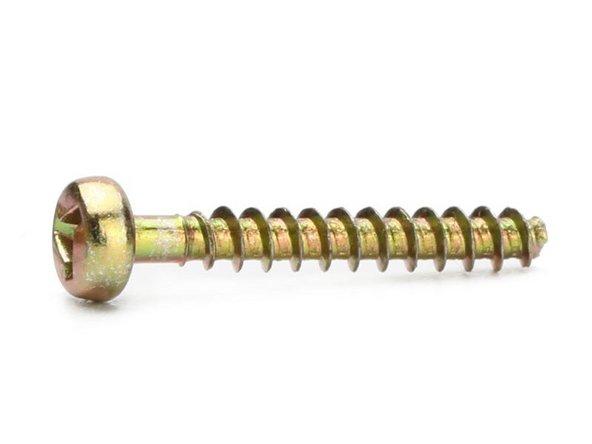
- The Tri-Wing (security) screws (indicated by the green arrows) are of the 'self-tapping' type and have a length of 1.90 cm and a diameter of 3 mm. (Image 2 is included for identification purposes only).
- The depth of the recess is 2.4 cm and it has a diameter of 6 mm. Image 3 indicates which version of the Tri-Wing screws are located in these (2x) recesses.
- Note: the plug is still REMOVED from the socket.
- If using the Tri-Wing screwdriver (See image 1 and check the note (including disclaimer) in the tool list), follow this step. Otherwise, proceed to step 5 (Part 2b)
- Loosen the two screws (marked by the 'green arrows', see previous step).
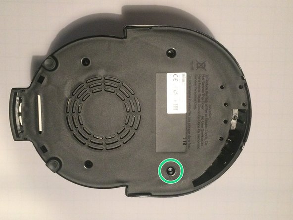
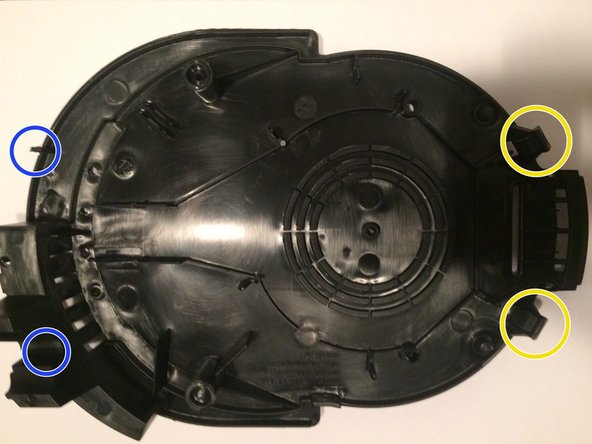
- It is not necessary to fully remove the screws from the bottom cover. If the screw, measured from the top, is 1.1 cm deep (in closed state that is 2.2 cm) in the recess, the bottom cover is 'loose' from the rest of the device. The bottom cover is now still held in place (fixed) by four tabs (see step 6).
- <Additional illustrations for bullet 3> In image 2: The screw (green circle) is no longer attached to the chassis in this position. Image 3 (inside of bottom cover) shows that it is not necessary to remove the screw completely.
- By the way: the plug is still OUT of the socket.
- Proceed to step 6.
- In this step (the workaround without a Tri-Wing screwdriver), a voltage tester is used (See image 1). Check the requirements for this voltage tester (See tool list, details).
- Place the voltage tester with your thumb and index finger perpendicularly (90 degrees) into the recess (See the 'green arrows' in step 3) and turn the voltage tester slightly left and right until the voltage tester has 'grip' on the screw (See image 2).
- Because the moment of gaining 'grip' is quite subtle, some practice will be required here. If there is grip on the screw, proceed to the next bullet.
- Hold the voltage tester in the perpendicular position and stabilize the situation by applying (significant) pressure with the palm of your hand (See image 3). With your other hand, the voltage tester must now be turned counterclockwise so that the screw comes loose. As the screw is unscrewed from the device, the pressure from your palm must decrease accordingly.
- If there is no longer any 'grip' (due to insufficient pressure and/or the voltage tester is/was not perpendicular), you must start again at bullet 2.
- Note: the screws do not need to be completely unscrewed from the device before the bottom cover comes loose! Tip: Loosen the screws (2 pieces) bit by bit, alternating between them, and check every now and then (carefully) whether the bottom cover is already starting to loosen. (See also Step 4 (2a), bullets 3 & 4, for further information)
- If it does not work immediately, it is wise to continue at another time (Tip: for example, the next day).
- By the way: the plug is still OUT of the socket.
- Check: the plug is still OUT of the socket!