Dell Latitude 3310 Teardown
ID: 144925
Description: In this guide, you will learn how to teardown...
Steps:
- Make sure you have a clean desk space with plenty of room to separate the components.
- Ensure any devices or peripherals plugged into the laptop are removed and set aside.
- Using the system dialog, power off the computer to prevent data loss.
- Loosen and remove all ten (10) M2.5x5 screws.
- Carefully remove the bottom plate of the laptop by prying it from the hinges and working around the edges.
- Take caution when removing the laptop hinges, as they are fragile and can break.
- Disconnect the battery cable from the motherboard.
- Be careful not to bend the pins in the female connector! Make sure to apply equal pressure on both sides of the white male connector.
- Remove the four (4) M2x3 screws - there is one at each corner of the battery.
- Lift away the battery and place it on a flat surface.
- For temporary storage, place the battery on paper and tape the battery connector.
- Remove the top of the sheet covering the RAM.
- Instructions for removing the RAM are accessible on the sheet that covers the RAM.
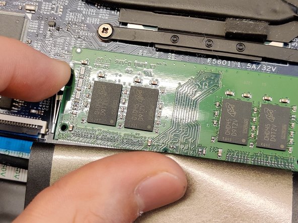
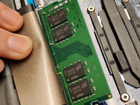
- Press the metal rails aside with your fingertips.
- Take the RAM out and place it on a flat surface.
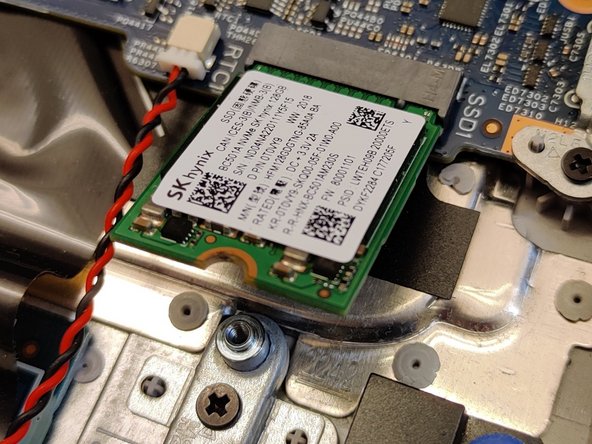
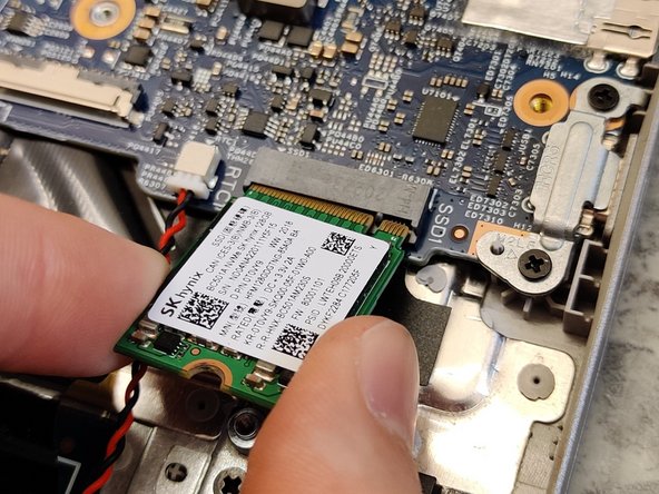
- Remove the single (1) M2x3 screw.
- Wiggle the M.2 disk away from the motherboard, then set it aside.
- The standoff consists of a single M2 screw that can be removed.
- Remove the single (1) M2x3 screw.
- Move the mounting plate aside.
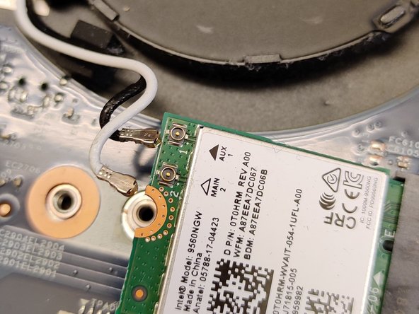
- Disconnect the antennas.
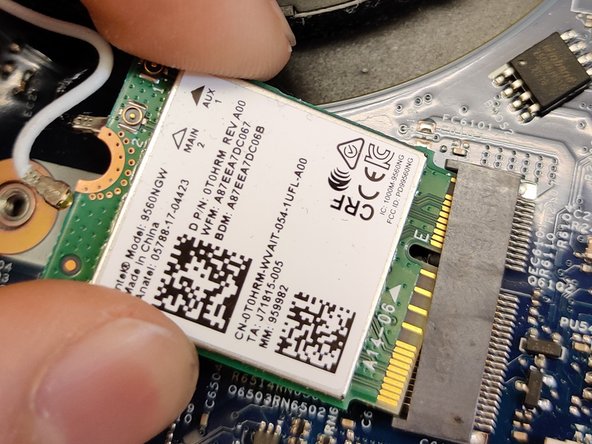
- Wiggle the card away from the motherboard.
- Rearrange the antenna cables for easier removal of the motherboard later.
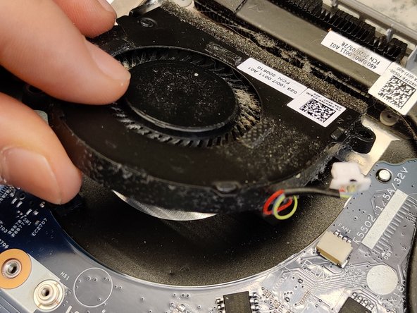
- Disconnect the fan from the header.
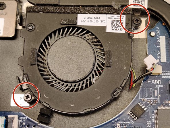
- Remove two (2) M2x3 screws.
- Set the fan aside.
- Take the opportunity to remove any dust from the fan.
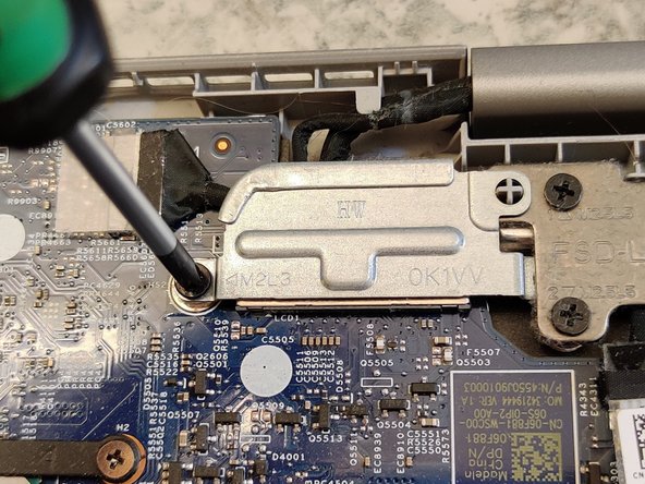
- Remove one (1) M2x3 screw, lift the DP-cable mounting bracket, and set it aside.
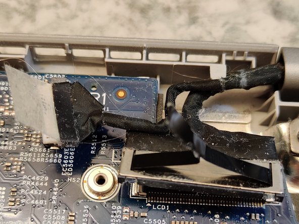
- Disconnect both cables.
- Remove the three (3) M2.5x5 screws.
- Lift the metal brackets.
- I usually do this by opening the laptop. Be careful while doing this to avoid lifting and bending the plastics under or back.
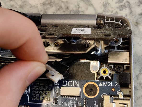
- Then disconnect the DC-cable.
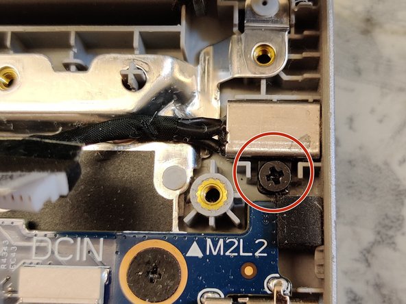
- You can remove the DC-connector by removing this screw. There are no markings, but I'd say this one is M2x2.
- Disconnect the marked cables. Make sure to lift up the locking tabs with a plastic tool. The CMOS and speaker cables are disconnected by pulling on the white connector at the end of the cable.
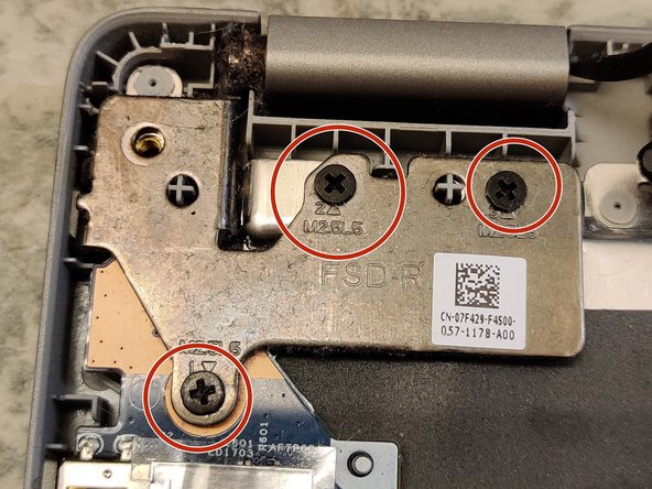
- Remove three (3) M2.5x5 screws and then lift the metal hinge.
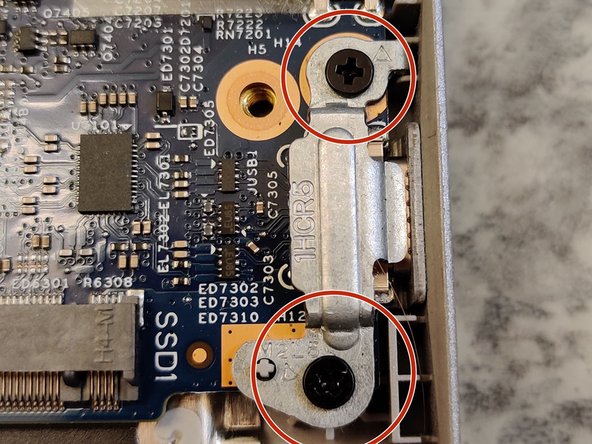
- Remove two (2) M2x5 screws that hold the metal bracket over the USB-C connector, then set it aside.
- Remove two (2) M2x5 motherboard screws.
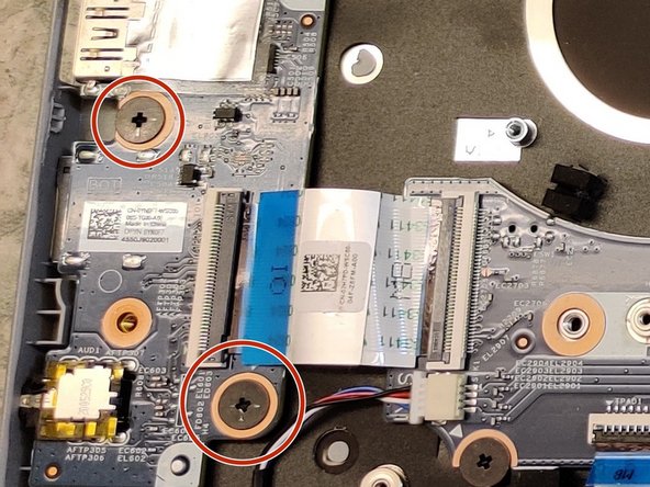
- Remove two (2) M2x2 I/O-board screws.
- Lift and remove the motherboard and I/O-board.
- Place them on an anti-static mat or similar surface.
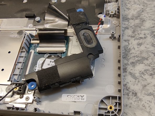
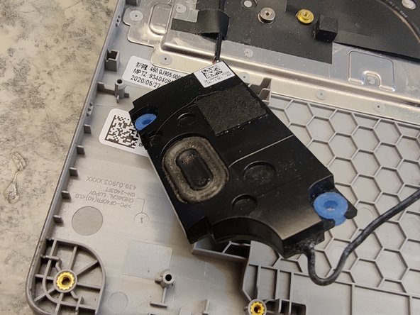
- You can simply lift the speakers away and carefully wriggle out the cables.
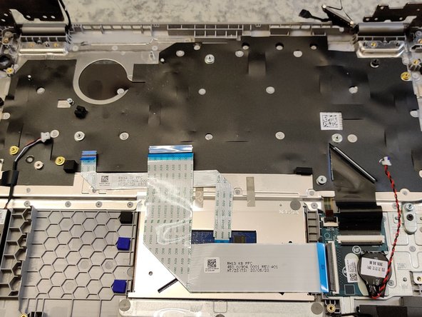
- I disconnected and removed the MB (motherboard) to KB (keyboard) cable and MB to TP (trackpad) cable.
- The CMOS battery is stuck to the frame with glue. The last cable goes to the keyboard that is hard mounted to the frame as well.
- Remove six (6) M2x2 screws.
- Lift and set the trackpad aside.
- The keyboard is hard mounted to the armrest.
- You should be able to lift the armrest up like one would open a laptop and then remove it from the screen.
- The screen can be opened by prying around the edges of the frame and then removing four (4) M2x2 or smaller screws to replace the LCD screen.