Logitech StreamCam (960-001286) USB-C Cable Replacement
ID: 144946
Description:
Steps:
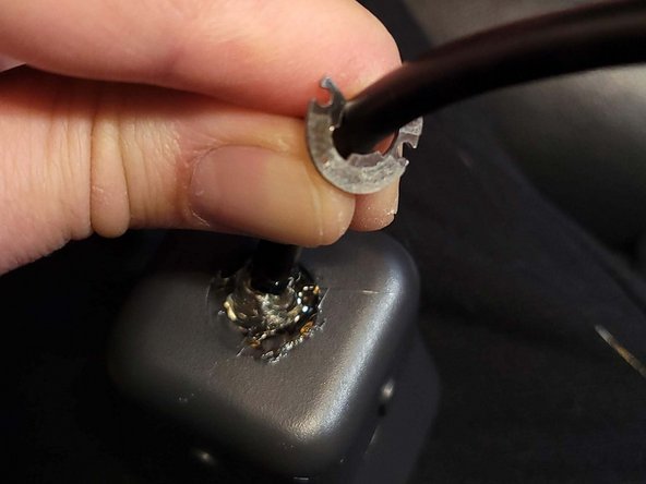
- Be mindful of keeping the lens glass away from abrasives when disassembling. Turn the camera over and use your plastic spudger (pry tool) to pop out the plastic ring obscuring two small screws.
- NOTE: many fixers may find that replacing only the distal USB-C plug is needed. In that case, you needn't open the camera or replace the cable -- just skip to the wiring explanation in step 4, and get a new USB 3.x type-A or type-C male plug.
- Once the screws are removed, the retention ring easily separates from the cable moulding with firm prying or pulling pressure. It's a C-clip with some light adhesive facing outward.
- After the retention clip is out, peering into the housing will reveal two identical 000 screws that hold the camera subframe to the outer shell. Remove these (they'll easily shake out if not pulled out with your screwdriver's tip).
- With the retention ring off, you can advance the cable moulding into the housing, and the entire camera subframe assembly should freely disengage from the outer shell.
- The cable's connection to the board is two-fold: unscrew the single grounding cable, then disengage the white plug by squeezing the wide surfaces with your thumb and forefinger then gently pulling outward.
- The entire cable may then be pulled outward, through the outer housing/shell port where the cable retention clip was fastened. (The white plug can be slightly manipulated to fit through.)
- The connector is a JST GH 1.25 10-pin. JST is the manufacturer, GH is the series; 1.25 is the pitch, the contacts being 1.25mm apart. (Thanks to comment by Oleg Vin for noting the type.)
- Fixers replacing the entire cable may choose to solder a new JST GH connector to their new cable before disassembly, reducing the time the camera sits in pieces. (Reuse the original ground wire for the cable sheath/shielding.)
- 2024.03.04 Warning: Due to reports and my own experience of failure to achieve 60fps, I believe the SSTX and SSRX pinouts are inverted. I will experiment and update the guide ASAP with any corrections.
- 20240310: swapping 10 with 9, and 7 with 6 (polarity reversals) has given me 1080 60fps on Win 10 with Logitech Capture, but now my Linux PC doesn't recognize the camera.
- In this guide, a 6-foot USB-3.0 extension cable (female and male type-A plugs) was the donor part. The female plug was cut off with several inches of cable, so that it could be repurposed; the male end and cable is used in this repair.
- Researching USB 3.0 cable wiring, SSRX+ and SSRX- appeared mapped to yellow and blue, respectively. With the donor cable used here, however, continuity testing proved unexpected wire color deviation. SSRX+ and SSRX- as pictured in the accompanying donor cable image yielded a successful camera repair.
- If the distal USB-C plug of the original cable is the only defect, you may alternatively or preferentially choose to replace it with a USB 3.0 type-C or type-A plug -- rather than replacing the entire cable. You can then retain the sturdy original retention collar and greatly simplify the soldering work.
- A video guide explaing the cables and how to map them to a standard USB 3 donor cable with USB-A connector is published here https://youtu.be/RvXXlFohyw0
- Soldering is the most challenging task of this repair, but beyond the scope of this guide. Always ensure adequate ventilation, and use respiratory and eye protection.
- The soldering results displayed in this guide are amateur and achievable by those with intermediate skills. Practice and patience are the key elements of success.
- After soldering, use a multimeter or stand-alone continuity tester to verify that each pin of the connector has continuity with only the expected USB plug contact, as mapped in the previous step.
- Each twisted pair of the cable has its own shielding that must be joined and linked to the black wire of board connector pin 8.
- Three screws hold the inner block. Removing this eases the task of threading through the board connector and insulated soldering work.
- Not pictured is application of insulation to the soldered connections. This is necessary to prevent short circuiting and equipment failure. Options include heatshrink tubing, liquid electrical tape, or hot glue, among other approaches.
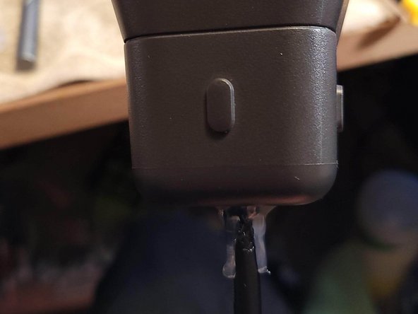
- Cable retention and strain relief is created with hot glue as pictured. Sugru is recommended as a clean, strong, and aesthetically pleasing alternative.
- The hot glue was applied two-fold: within the housing (through the rear cutout), then at the C-clip flange. The C-clip was screwed down atop the second glue application while it was still cooling.