PlayStation VR Infrared Range Finder Replacement
ID: 145324
Description: If your PlayStation VR Headset is experiencing...
Steps:
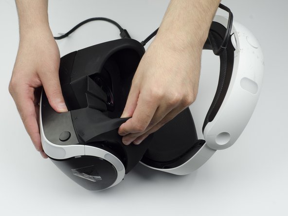
- Peel back the rubber covering around the lenses to remove the surrounding plastic eyepieces.
- Unscrew four 13 mm screws with a PH #000 screwdriver.
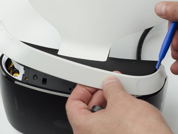
- Using the plastic opening tool, carefully pry the white plastic panel free from the side of the headset. Repeat this action for the opposite side.
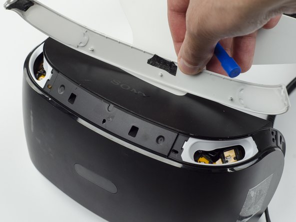
- Use the plastic opening tool to pry the top white plastic panel free from the headset.
- Do not try to remove the bottom plastic panel. There is a screw attaching it that must be removed first.
- There may be a small amount of adhesive attaching the top panel to the headset, in which case you may need to use a bit more force to remove the panel.
- Flip the headset over.
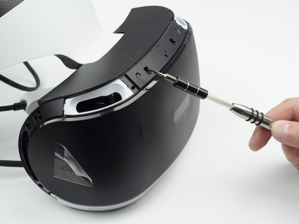
- Using a PH #000, unscrew the 7 mm screw found on the bottom of the headset.
- Using the plastic opening tool, pry the bottom white plastic panel loose and remove it from the headset.
- There is adhesive attaching the panel to the headset, in which case it will take more force to remove the panel.
- Unscrew the two 7 mm screws from the top of the headset.
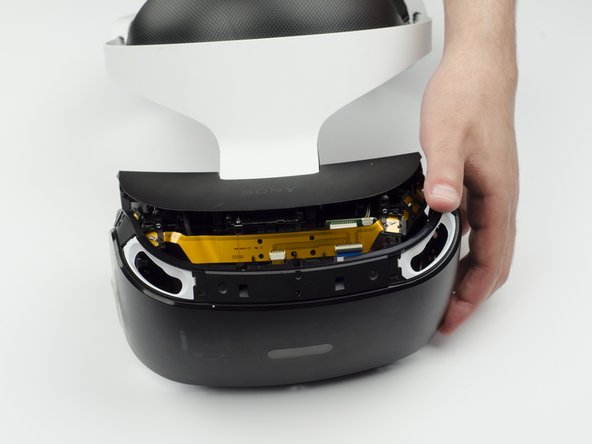
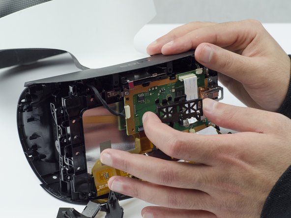
- Using your fingers, carefully pry the black front panel free from the headset.
- We recommend that you start the removal from the sides by pulling them forward.
- There is adhesive holding the front panel in place, which means you will need a bit of extra force to remove it.
- Unscrew the four silver 6 mm screws in each corner using a PH #000 screwdriver.
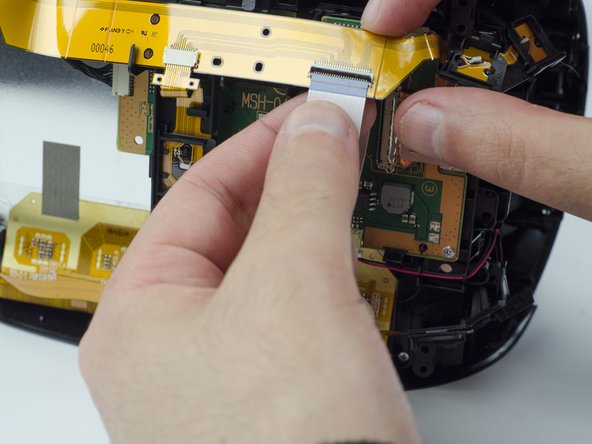
- Lift the small silver latch attaching the ZIF (zero insertion force) connector to the circuit board.
- Carefully pull the end of the white ribbon connector from its slot.
- Be careful not to damage or dirty the ribbon connector.
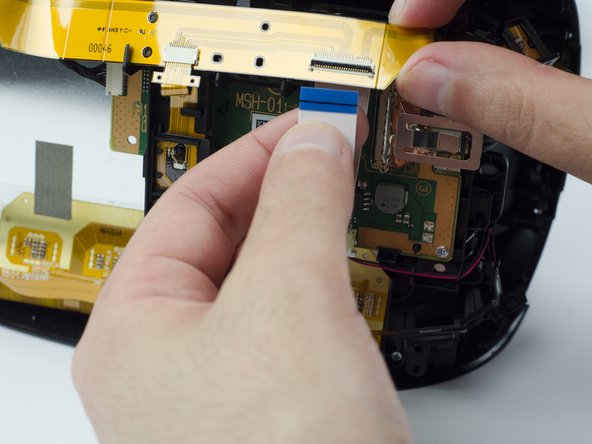
- Unhitch the yellow led connector ribbon and move it aside.
- Be careful not to damage or dirty the ribbon connector.
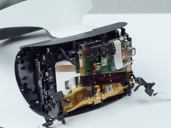
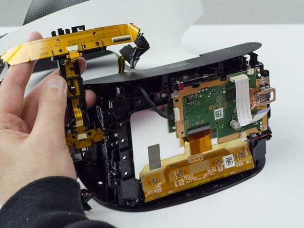
- Carefully pry the black plastic piece attaching the yellow ribbon to the headset away from the green circuit board.
- Remove the yellow LED ribbons and black plastic connecting piece from the headset.
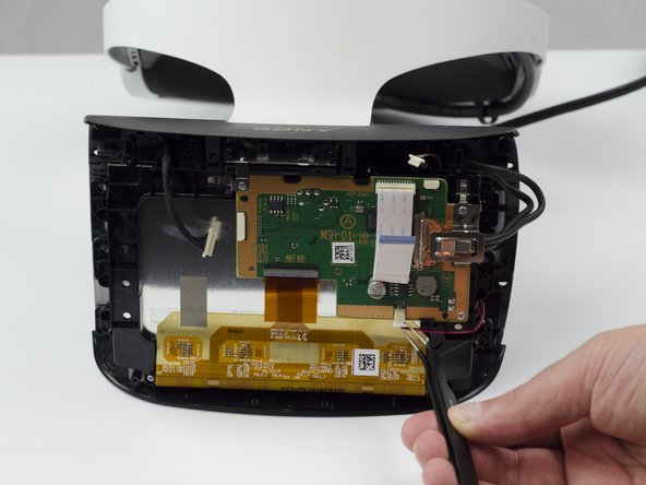
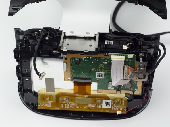
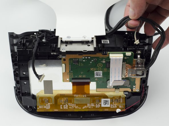
- Using the tweezers, unplug the three (one black bundled, two multi colored bundled) connector cables from their ports along the circuit board.
- Flip the headset over.
- Unscrew the two 7 mm screws near the lenses with a PH #000 screwdriver.
- Flip the headset back over.
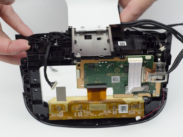
- With your fingers, carefully pry the top black plastic panel free.
- Unscrew one silver 4 mm screw from the white plastic band connecting the rest of the headset.
- One 4 mm screw with a PH #000 screwdriver.
- Even though there are two, only one of the silver screws needs to be unscrewed.
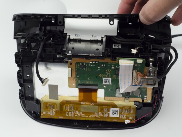
- Move the top black wires aside.
- Using a finger, press the black plastic tab up to loosen the white connector piece.
- Slide the white plastic connector piece back and lift up to remove it.
- Unscrew the five silver 6 mm screws from the circuit board.
- Five 6 mm scews with a PH #000 screwdriver.
- Using your fingers, lift up on the sides of the black plastic piece holding the circuit board in place.
- There are small plastic tabs on the side that latch the piece in place that need to be lifted in order to remove it.
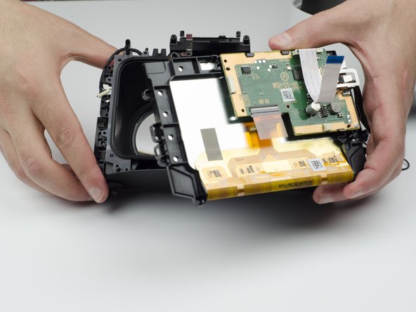
- Carefully lift the circuit board out of the headset and set aside.
- Take care not to touch the screen.
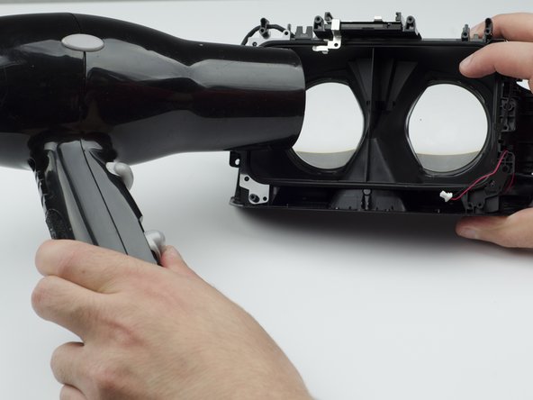
- Using a hairdryer (or heatlamp), warm the area around the lenses. This will help loosen them for removal.
- Using a glass cloth (or any cloth with soft fibers), carefully press on the lenses until they pop out of place.
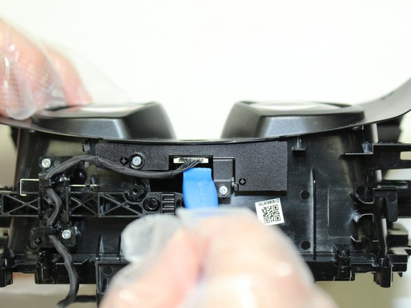
- Remove two silver 4mm screws from the bracket assembly containing IMU/infrared range finder board using a Phillips #00 screwdriver.
- Use an opening tool to pry the connecter from the board.
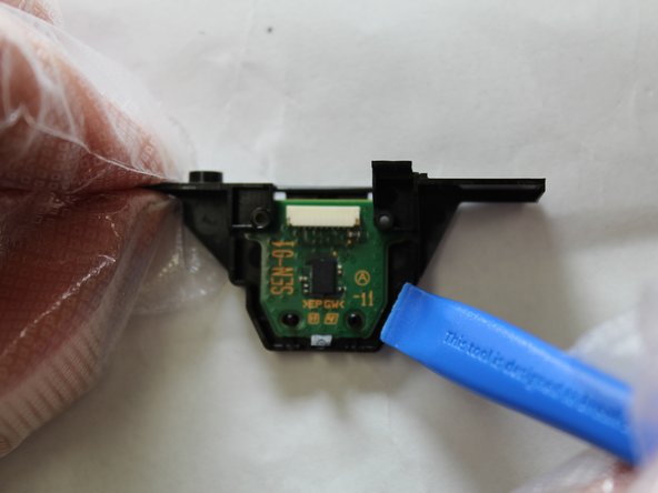
- Gently pry outward with an opening tool to remove the board from the bracket assembly.
- Desolder the faulty infrared range finder from the backside of the board.