PlayStation VR Rear LED Tracker Board Replacement
ID: 145453
Description: This is a short guide on how to easily replace...
Steps:
- Use your hands to remove the foam piece in the headband.
- Use the iFixIt Opening Tool to pry the top and bottom trim pieces off of the rear band assembly.
- Remove a total of four 5 mm screws from inside the left and right sides of the headband using a Phillips #00 screwdriver.
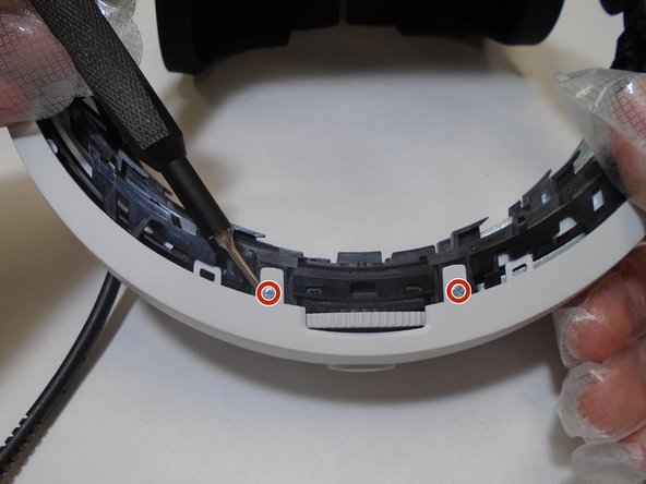
- Remove three silver 5 mm screws that are securing the rear white cover of the band using a Phillips #00 screwdriver.
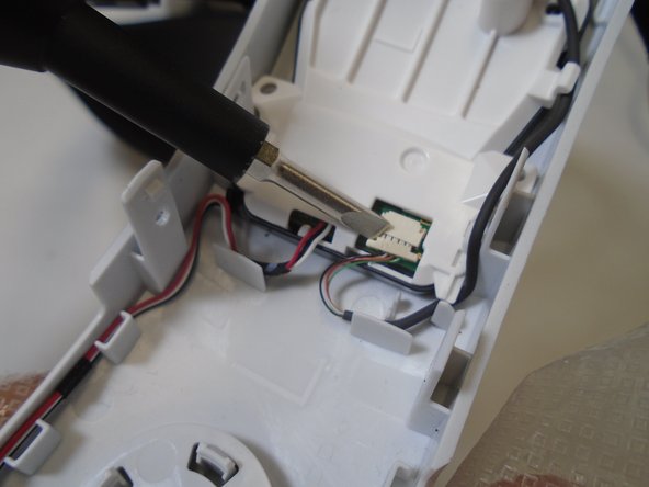
- Remove the 6 mm screw from the retainer securing wires to the rear band assembly using a Phillips #00 screwdriver.
- Use a spudger to flip up the retaining flap connected to the rear LEDs.
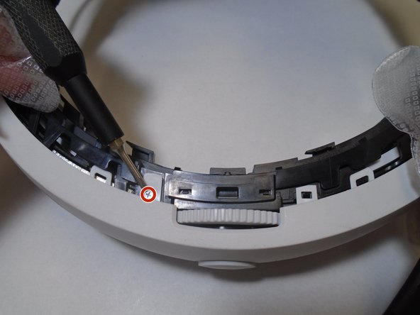
- Remove the single 5 mm screw from the center of the headband adjuster using a Phillips #00 screwdriver.
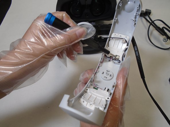
- Gently pry the adjuster assembly away from the rear headband using an opening tool.
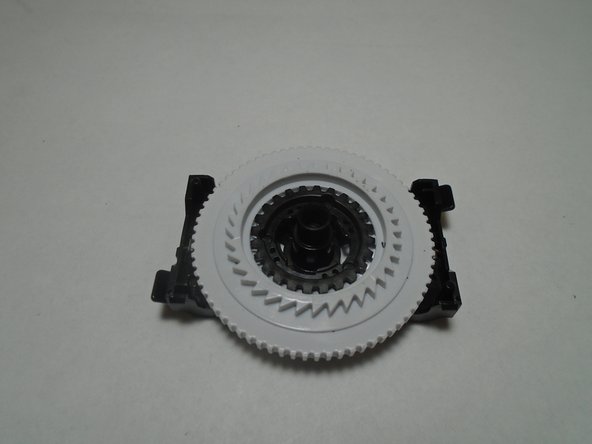
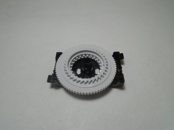
- Disassemble the adjuster assembly spring, small gear, large gear, and bracket in order to replace the broken component.
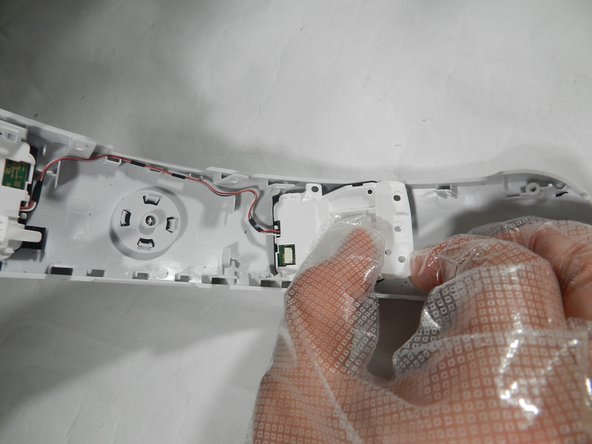
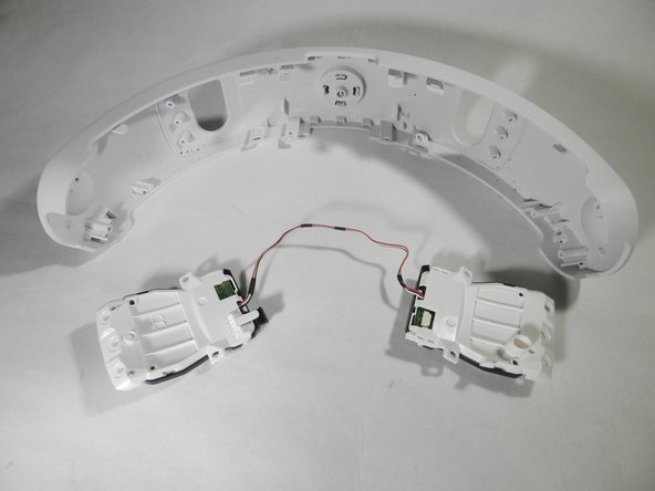
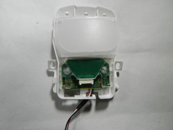
- Once the rear headband is removed, both rear LED tracker boards can be identified as the white components labelled 'L' and 'R' on the rear of the band.
- Remove the single 5 mm screw from each of the LED tracker boards using a Phillips #00 screwdriver.
- Gently pull up and slide each tracker board outward, away from the center of the band, in order to free it from the rear headband shell.
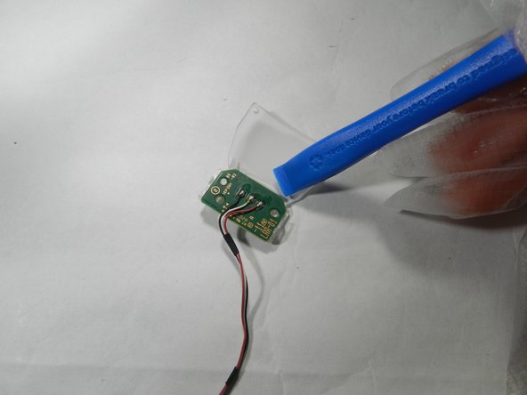
- The tracker board assembly is comprised of two shell halves.
- Gently pry on the black tabs on the outward edge of the shell to free the two halves from each other.
- Then gently pry outward on the internal tracker board to free each one from the opaque lens.
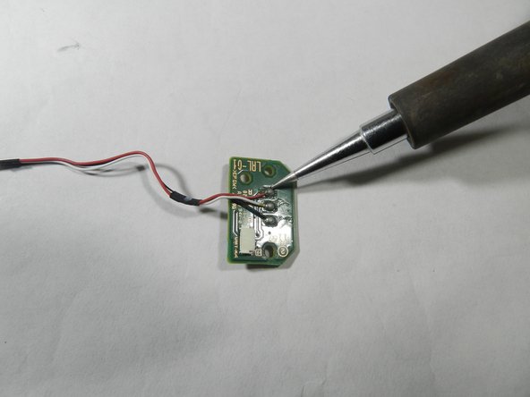
- Use a soldering iron in order to remove the three wires (black, white, red) from the faulty tracker board.