Blackvue DR650GW-2CH Dashcam RTC Battery Replacement
ID: 145528
Description: After several years of use, does your Blackvue...
Steps:
- Using a small jeweller's flat bladed screwdriver, carefully pry up one corner of the plastic window covering the WiFi LED on the end of the dashcam.
- Once you've pried the window slightly, you can use a plastic spudger to gently lift up the window without damaging it.
- Remove the window and set it aside.
- If you're careful, the adhesive will be sticky enough to replace the window securely when you're done with this repair!
- Once the window is removed, you should see a screw adjacent to the circuit board.
- Proceed to remove the screw using your Philips head screwdriver.
- Near the opposite end of the dashcam from where you removed the plastic window, you'll see a small opening on the side of the end-cap.
- Using a small flat bladed screwdriver, press on the plastic tab that you find inside that opening.
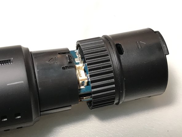
- Pressing on that tab should release the plastic end-cap so that you can slide it off the end of the dashcam's cylindrical body.
- The 3rd photo shows the end-cap after it's been removed.
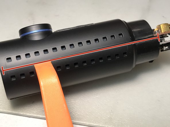
- Next step is to separate the two halves of the cylindrical dashcam body. I used an old credit card as well as a spudger tool for this step.
- Starting from the right end, work your way carefully along the horizontal crack between the two halves using a spudger and/or credit card. Be patient, don't use too much force or you may break one or more of the internal plastic tabs.
- Once you've loosened the tabs holding one side of the body, turn the dashcam over and loosen the other side.
- In the 3rd photo, you can see the location of 2 of the internal tabs holding the body together, in the small opening betwen halves. There are 4 of these internal tabs on each side.
- Once both sides are loosened, you can separate the top and bottom halves of the dashcam body.
- Be careful not to break the red/black wires going to the piezo-electric speaker on the upper half.
- Inside the dashcam, there are two stacked circuit boards. Using a plastic pry or spudger tool, gently pry the top circuit board up from the bottom circuit board.
- There are 3 connectors between the 2 circuit boards holding them together. In the 2nd photo, for reference you can see these 3 connectors (outlined in red), once the boards have been separated. You can also see the bottom side of the upper circuit board here, where the RTC battery is found.
- Once you've separated the 2 circuit boards, you'll see the RTC battery mounted on the bottom side of the upper board. In the first photo you'll see it's covered by a piece of clear rubber tubing, for insulation.
- Carefully slide off the clear rubber tubing/insulation, and set it aside for replacement later.
- The 2nd photo shows the RTC battery after the insulation has been removed.
- Using a soldering iron and desoldering pump, carefully heat the 2 battery terminals and suck off the solder.
- A pair of tweezers may be helpful to lift and remove the battery once the solder has been heated.
- Remove the old battery and clean off any excess solder from the circuit board battery terminals.
- The battery used is a Seiko MS621FE FL11E 3V 5.5mAHr Rechargeable Battery Super Capacity.
- The battery terminals are pre-bent to both lie flat against the circuit board when the battery is oriented with the correct side up.
- Position the new battery over the circuit board so its terminals line up with the corresponding pads on the circuit board.
- Solder the new battery to the circuit board, being careful not to overheat the circuit board traces nor create any shorts.
- Slide the rubber tubing/insulation onto the new battery.
- Carefully align and reconnect the 3 connectors between the two stacked circuit boards together, then reassemble the dashcam body and you're done!