Jura Impressa S Model Water Boiler repair/replacment
ID: 146897
Description: The steam valve is located behind the rotary...
Steps:
- Always remove the power cord from the wall outlet.
- Lift out the coffee tray
- Remove the lid sealing the coffee bean container
- Remove all of the coffee beans you can possibly remove.
- Pull the adjuster of the coffee bean grinder straight up
- Remove the four T15 Torx screws
- Remove the cup heat plate.
- It can be opened like a book.
- Below the cup heat plate there are three more T15 Torx screws. Remove them.
- The top cover is now free. Lift ´er up and set ´er aside.
- Remove the knob for the steam valve by simply pulling it off.
- The front cover is secured with a Torx T15 screw. Remove it.
- Now the front cover can be opened like a door for a few inches. The hinge is on the left.
- Various hoses hinder the further opening of the front cover. You need to remove the steam valve keypad from the cover.
- Use a spudger to lift the two notches at the top of the front cover a bit to release the keypad at the top.
- Lift the keypad upwards and pull it to the back. The steam pipe will slide out from its connection.
- All hoses can remain connected.
- Remove the silicone hose leading from the steam valve to the coffee spout. If it is secured with a cable tie which must be removed first.
- The front cover is now free and can be opened.
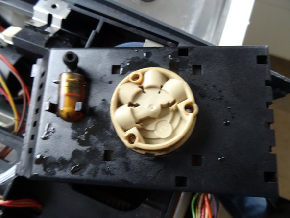
- The first picture shows the front of the unit, the other two pictures the back.
- Loosen the clips on the black cover and carefully lift it off.
- Pull out all hose connections. There are small O-rings at the ends, they may also be stuck in the valve body. Remove the O-rings and replace them with new ones when reassembling.
- Note exactly where which hose is connected, e.g. by taking a photo, or mark the connection points. In the third photo, the connections are marked (this may also look different on some models):
- H = Heating
- S = Steam generator on
- S = Steam generator off
- A= Pressure release valve (elbow)
- P = Pump
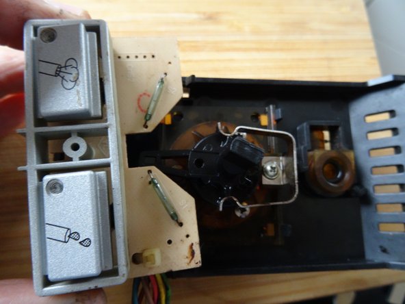
- Carefully unclip the circuit board with the switches. Caution: the two reed switches (marked green) are made of glass and break very easily.
- Release the two latches on the pushbutton board.
- Lift the board very carefully by the bottom and pull it off the unit.
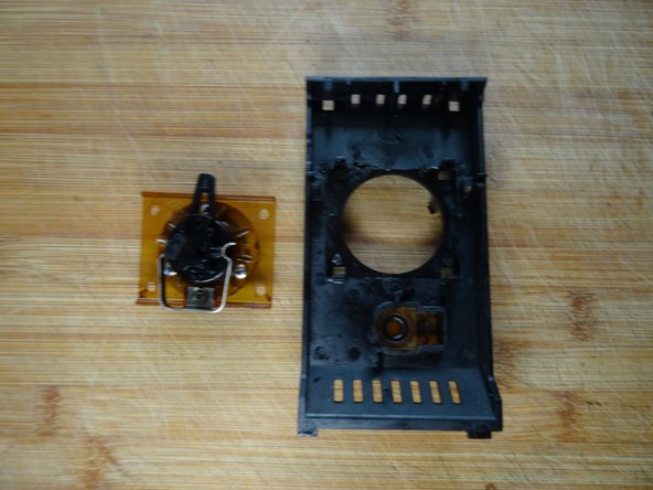
- The unit is free.
- Loosen the four latches on the steam valve.
- Gently lift the steam valve upwards.
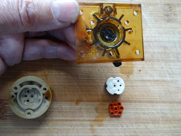
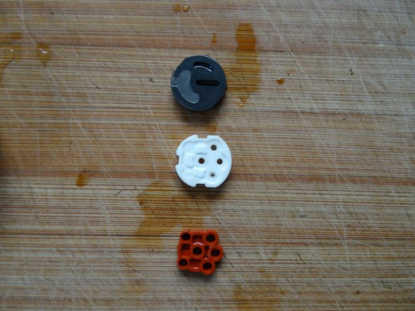
- In the next steps you have to be very careful: inside the valve there are two ceramic discs that stick easily. If they fall off, they break easily and are broken.
- Loosen the three Phillips screws on the black valve bonnet and very slowly lift it upwards off the valve body.
- Turn the valve bonnet over. The molded seal becomes visible. Make sure that it is seated correctly; it must be seated in the valve body again later, otherwise the valve will not work.
- Carefully lift out the molded seal and the two ceramic washers. Note the exact installation position.
- Now you can clean all parts. If the seal is defective, you need to replace it.
- Pay close attention to the correct orientation when assembling.