Microsoft Surface Pro 5 Battery Replacement
ID: 146981
Description: Use this guide to replace a worn-out or dead...
Steps:
- Completely power off the Surface before you begin disassembly.
- If the screen's glass is cracked, keep further breakage contained and prevent bodily harm during your repair by taping over the glass. Lay overlapping strips of clear packing tape over the display until all the glass is covered. Wear safety glasses to protect your eyes.
- Heat an iOpener and apply it to the right edge of the Surface's screen for two minutes.
- You may need to reheat and reapply the iOpener several times to get the Surface warm enough. Follow the iOpener instructions to avoid overheating.
- A hair dryer, heat gun, or hot plate may also be used for more heat, but be careful not to overheat the Surface—the screen and internal battery are susceptible to heat damage.
- Take note of the screen adhesive layout before continuing:
- These areas only contain adhesive and are safe to cut.
- The display board and flex cables sit here close to the edge. Cut very carefully and do not insert the pick as deep under the display.
- Fragile antenna cables lie under this part of the screen. Carefully follow the procedure to avoid damaging them. The adhesive is also the thickest here.
- Insert an opening pick into the speaker opening on the screen and slide the pick under the glass. Do not press the pick into the speaker grille, as the grille is easily torn.
- Don't insert the opening pick any deeper than the black bezel on the side of the screen. Inserting the pick too far may damage the LCD.
- Rotate the pick toward the bottom of the Surface to slide it underneath the lower edge of the speaker cutout.
- Slide the pick down the right edge of the Surface to slice through the adhesive under the screen.
- Throughout the rest of the procedure, if you encounter significant resistance while sliding the pick, stop and reheat the section you're working on. Applying too much pressure with the pick can crack the glass.
- Leave this opening pick in the right edge to prevent the adhesive from resealing.
- Reheat the iOpener and apply it to the bottom edge of the Surface's screen for two minutes.
- You may need to reheat and reapply the iOpener several times to get the Surface warm enough. Follow the iOpener instructions to avoid overheating.
- A hair dryer, heat gun, or hot plate may also be used for more heat, but be careful not to overheat the Surface—the screen and internal battery are susceptible to heat damage.
- Insert a new opening pick into the bottom right corner and slide it around the corner toward the bottom edge.
- Don't insert the opening pick any deeper than the black bezel on the side of the screen. Inserting the pick too far may damage the LCD.
- Slide the pick along the bottom edge of the Surface to cut through the screen adhesive.
- Leave this pick in the bottom edge to prevent the adhesive from resealing.
- Reheat the iOpener and apply it to the left edge of the Surface's screen for two minutes.
- You may need to reheat and reapply the iOpener several times to get the Surface warm enough. Follow the iOpener instructions to avoid overheating.
- A hair dryer, heat gun, or hot plate may also be used for more heat, but be careful not to overheat the Surface—the screen and internal battery are susceptible to heat damage.
- Insert a new opening pick into the bottom left corner and slide it around the corner toward the left edge.
- Take care cutting under the lower 2.5 inches (65 mm) of the left edge. Do not insert the opening pick more than 1/8 inches (3 mm) here. The display cables sit near this part of the bezel and are easily damaged. Once past the display cable area, do not insert the pick past the bezel.
- Slide the pick along the left edge of the Surface to cut through the screen adhesive.
- Leave this pick in the left edge to prevent the adhesive from resealing.
- Reheat the iOpener and apply it to the top edge of the Surface's screen for two minutes.
- The adhesive is thickest along this edge, and you may need to reheat and reapply the iOpener several times to get the Surface warm enough. Follow the iOpener instructions to avoid overheating.
- A hair dryer, heat gun, or hot plate may also be used for more heat, but be careful not to overheat the Surface—the screen and internal battery are susceptible to heat damage.
- Round the left corner with the opening pick and slide it along the top edge of the Surface. Stop when the pick is 2.75 inches (70 mm) away from the left edge.
- The next 6 inches (15 cm) of the top edge of the case is covered by the left and right antennas, which sit between the case and the screen bezel. Follow the next steps carefully to avoid damaging the antennas.
- Insert the point of a pick under the display where you just stopped cutting. Do not insert the pick deeper than the edge of the bezel.
- Carefully roll the pick to the right, pressing the long edge of the pick into the screen adhesive underneath the bezel, cutting the adhesive as you go. Do not slide the pick along the edge of the Surface.
- Keep the pick parallel to the screen throughout the whole procedure so that it doesn't catch on the antennas. Do not press the pick against the case.
- Repeat this motion of inserting the point of the pick where you just cut, and rolling to the right all along the top edge of the Surface, until the pick is 2.5 inches (64 mm) from the right edge of the Surface.
- Once you cut the adhesive over the antennas (8.5 inches, or 22 cm, away from the left edge), slide the pick the rest of the way along the top edge of the surface and round the top right corner to slice through any remaining adhesive.
- Very slowly lift the screen assembly away from the Surface case. If you encounter any resistance, stop and check that all the adhesive is separated.
- Do not remove the screen yet. It is still connected to the motherboard by two cables.
- Use an opening pick to cut through any remaining adhesive.
- The flash lens may fall out of the Surface case. Keep track of the lens and return it to its cutout in the case during reassembly.
- Lift the top of the screen assembly away from the case while sliding the bottom of the screen closer to the motherboard display connectors.
- Gently lay the screen down on the case with the connectors facing up. Take care to avoid creasing the display cables.
- Use an opening pick to pry up one edge of the EMI shield covering the display board.
- Repeat this procedure at different points around the shield until it is free.
- Try not to deform the shield too much—you will need to reinstall it during reassembly.
- Lift the EMI shield away from the display board and remove it.
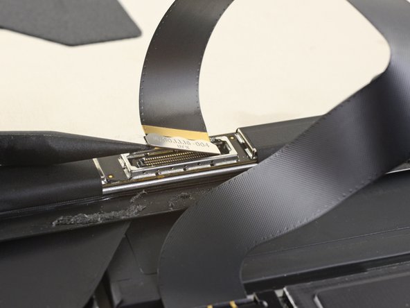
- Use the flat end of a spudger to pry the display interconnect cable straight up and out of its socket on the board.
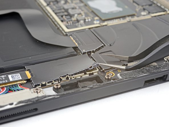
- Insert one point of a pair of pointed tweezers into a gap in the edge of the EMI shield covering the digitizer connector.
- Use the tweezers to pry the EMI shield away from the display as much as you can without bending it.
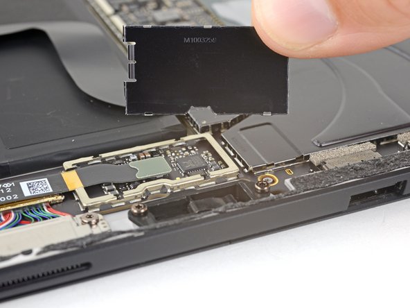
- Repeat this procedure at different points around the shield until it is free. Remove the shield.
- Try not to deform the shield too much—you will need to reinstall it during reassembly.
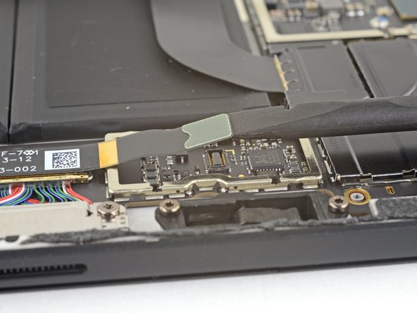
- Pull the rest of the shield off of the digitizer connector and remove it.
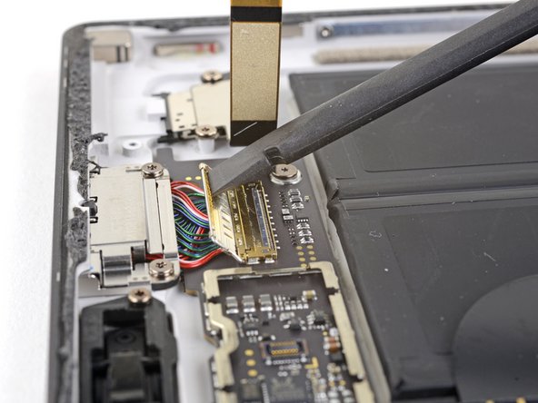
- Use the tip of a spudger to pry the digitizer connector straight up and out of its socket on the screen.
- Remove the screen assembly from the Surface.
- During reassembly, pause here and follow this guide to replace the screen adhesive.
- Use the point of a spudger to pry the microphone connector straight up and out of its socket on the motherboard.
- Use a T5 Torx driver to remove the four screws securing the antenna support:
- Three 4.5 mm screws
- One 6 mm screw
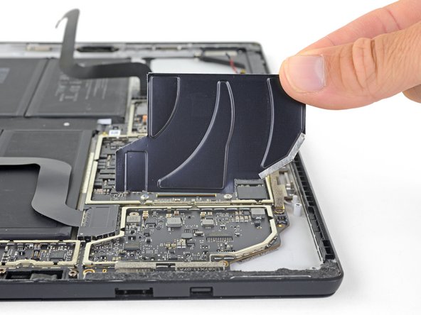
- Use a spudger to lift the antenna support out of its recess in the Surface.
- Remove the antenna support.
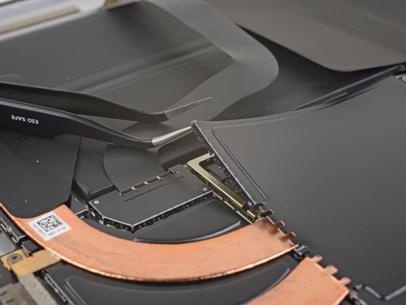
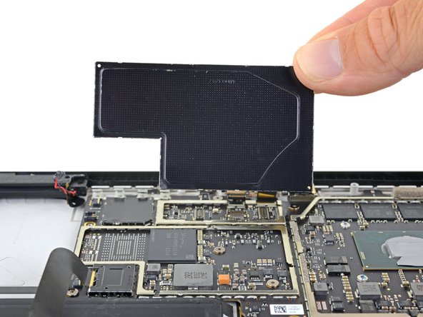
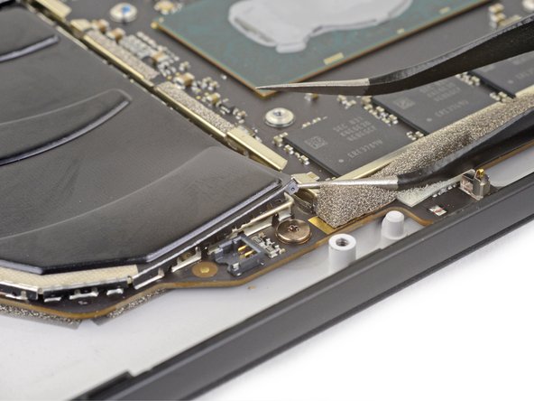
- Insert one point of a pair of pointed tweezers into a gap in the corner of the EMI shield covering the heat sink.
- Use the tweezers to pry the EMI shield away from the motherboard as much as you can without bending it. Do not remove it yet.
- Try not to deform the shield too much—you will need to reinstall it during reassembly.
- Take care not to puncture the battery with the tweezers while working on this shield.
- Repeat the last step for each corner of the EMI shield covering the heat sink.
- Remove the heat sink shield.
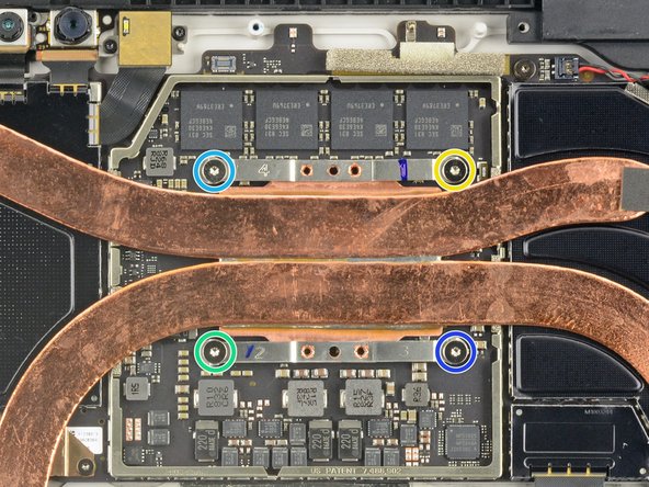
- Remove the nine Torx screws securing the heat sink:
- Five 2.6 mm-long T3 screws
- Four 3.3 mm-long T5 screws
- During reassembly, tighten the heat sink screws in the following criss-cross pattern, one turn at a time, until they're tight:
- Screw 1
- Screw 2
- Screw 3
- Screw 4
- Use the flat end of a spudger to gently pry the heat sink straight up and off of the CPU.
- Take care not to dent or crease the heat sink pipes during removal.
- During reassembly, make sure to properly clean the heat sink and CPU, and apply new thermal paste.
- Use the point of a spudger to lift the left speaker connector out of its socket on the motherboard.
- Use the point of a spudger to flip up the small locking flap securing the volume and power button cable ZIF connector.
- Slide the volume and power button cable straight out of its socket on the motherboard.
- Use the point of a spudger to lift the right speaker connector out of its socket on the motherboard.
- Use a T5 Torx driver to remove the two screws securing the right speaker:
- One 6 mm screw
- One 3.7 mm screw
- Use a spudger to lift the left edge of the right speaker so that it clears the components around the speaker.
- With the left edge lifted, slide the speaker to the left, straight out of its recess in the case.
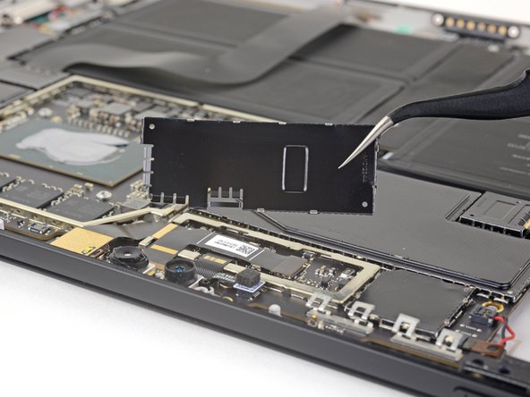
- Insert one point of a pair of pointed tweezers into a gap in the corner of the EMI shield covering the camera connectors.
- Use the tweezers to pry the EMI shield away from the motherboard as much as you can without bending it.
- Repeat this procedure at different points around the shield until it is free. Remove the shield.
- Try not to deform the shield too much—you will need to reinstall it during reassembly.
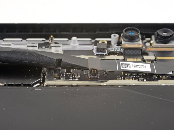
- Use the flat end of a spudger to pry the front-facing camera connector up and out of its socket on the motherboard.
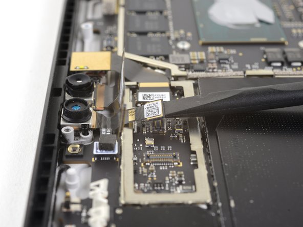
- Use the flat end of a spudger to pry the face-detection camera connector up and out of its socket on the motherboard.
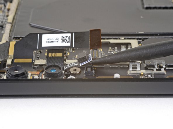
- Use the flat end of a spudger to pry the rear-facing camera connector up and out of its socket on the motherboard.
- Use the flat end of a spudger to pry the microphone connector up and out of its socket on the motherboard.
- Insert one point of a pair of pointed tweezers into a gap in the corner of the EMI shield covering the microSD card reader connector.
- Use the tweezers to pry the EMI shield away from the motherboard as much as you can without bending it.
- Repeat this procedure at different points around the shield until it is free. Remove the shield.
- Try not to deform the shield too much—you will need to reinstall it during reassembly.
- Take care not to puncture the battery with the tweezers while working on this shield.
- Use the flat end of a spudger to pry the microSD card reader connector up and out of its socket on the motherboard.
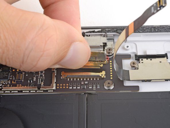
- Use the flat end of a spudger to lift the flap that sits over the SurfaceConnect port connector.
- Slide the SurfaceConnect port connector out of its socket on the motherboard.
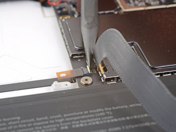
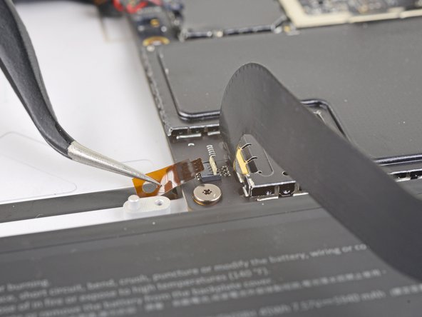
- Use the point of a spudger to flip up the small locking flap securing the headphone jack cable ZIF connector.
- Slide the headphone jack cable straight out of its socket on the motherboard.
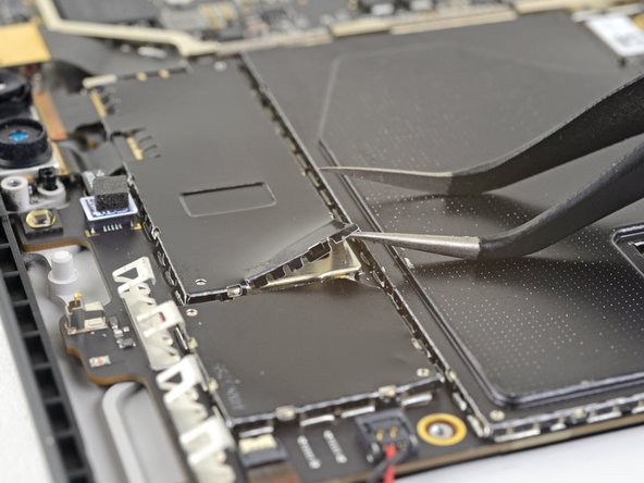
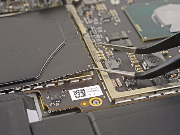
- Insert one point of a pair of pointed tweezers into a gap in the corner of the left-most of the remaining large EMI shields.
- Use the tweezers to pry the EMI shield away from the motherboard as much as you can without bending it.
- Repeat this procedure at different points around the shield until it is free. Remove the shield.
- Try not to deform the shield too much—you will need to reinstall it during reassembly.
- Take care not to puncture the battery with the tweezers while working on this shield.
- Repeat the previous step to remove the remaining large EMI shield from the right side of the motherboard.
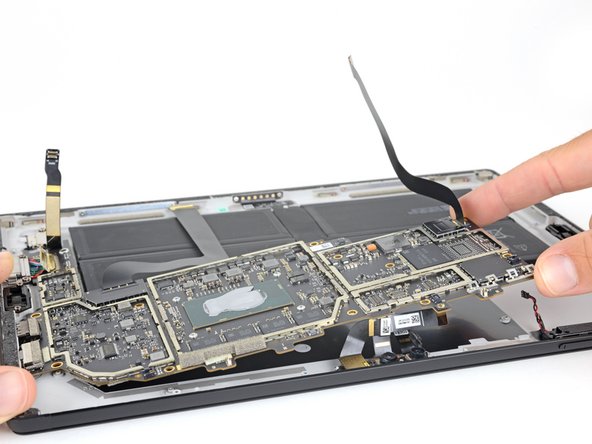
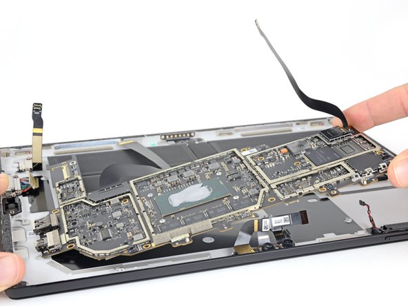
- Use a T3 Torx driver to remove the eight 2.5 mm screws securing the motherboard.
- Lift the non-port-side of the motherboard up slightly, just enough so that it clears the components around it and the edge of the case.
- Slide the motherboard away from the ports. Make sure the ports are completely out of their slots in the case before removing the motherboard.
- Remove the motherboard.
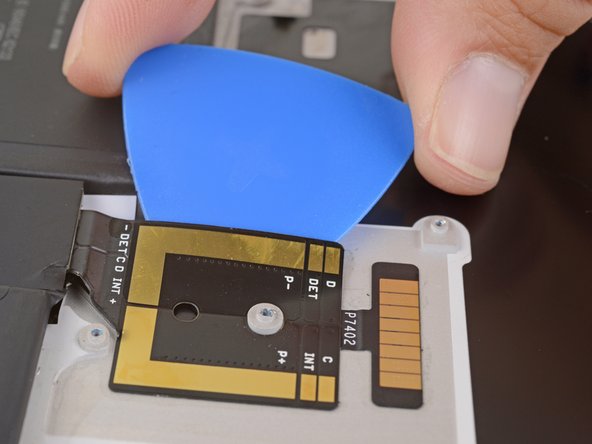
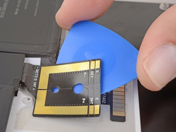
- Heat an iOpener and apply it to the battery connector for two minutes to soften the adhesive securing the connector to the case.
- Starting at the edge closest to the battery, slide an opening pick under the battery connector to separate the adhesive underneath.
- Make sure the battery connector is completely free from the case.
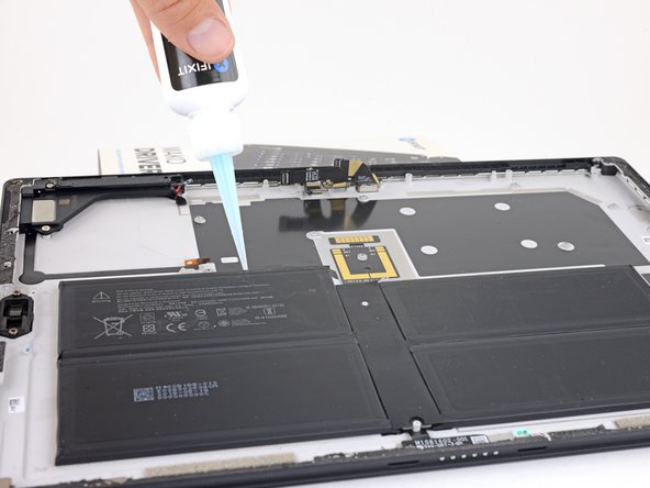
- Prop the top edge of the Surface up a couple inches so the whole Surface slopes towards the bottom edge.
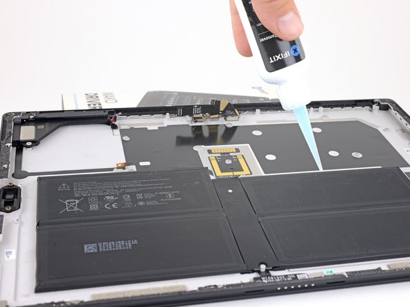
- Apply adhesive remover or high-concentration (90% or higher) isopropyl alcohol to the top edge of the battery.
- If you are using adhesive remover, follow these preparation steps first.
- Let the adhesive remover sit and soak into the adhesive for 2–3 minutes before continuing.
- Take care not to puncture or bend the battery with your tools—a punctured or bent battery may leak dangerous chemicals or cause a thermal event.
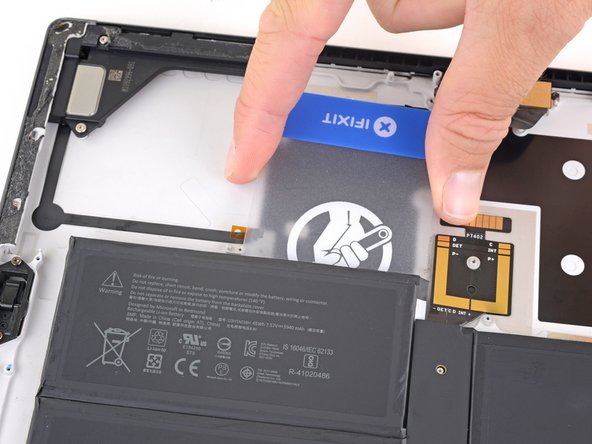
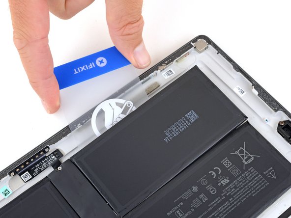
- Slide a plastic card under the left side of the top edge of the battery.
- If you encounter significant resistance at any point during this procedure, stop, apply a little more adhesive remover, and wait for it to soak in.
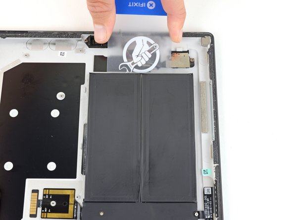
- Slide the card side to side under the upper left battery cell to slice through the adhesive underneath.
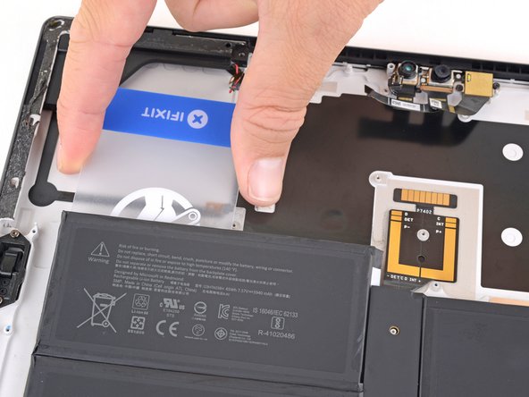
- Slide the plastic card around the left edge of the battery and under the bottom left battery cell.
- Slide the card side to side under the bottom left cell to slice through the adhesive underneath.
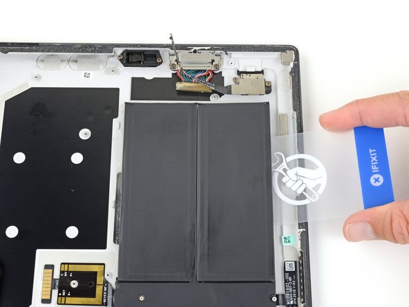
- Repeat the previous two steps for the right side of the battery to release the two right cells from their adhesive.
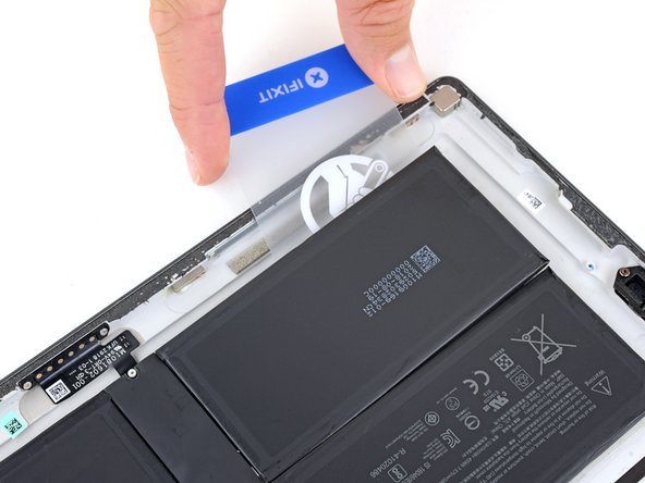
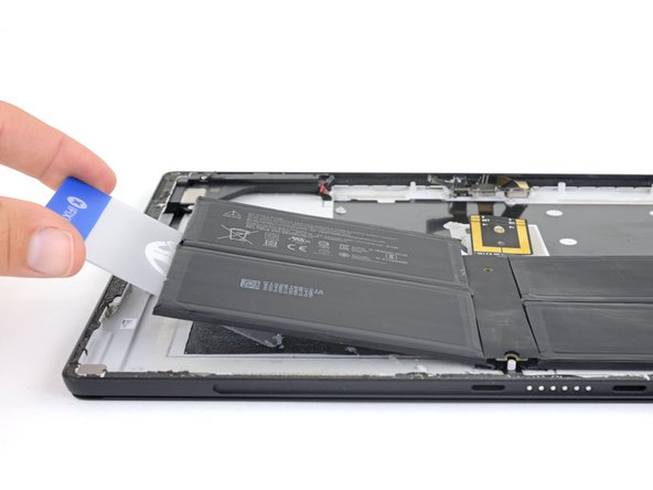
- Lift each side of the battery with a plastic card and make sure all the adhesive is separated from the battery.
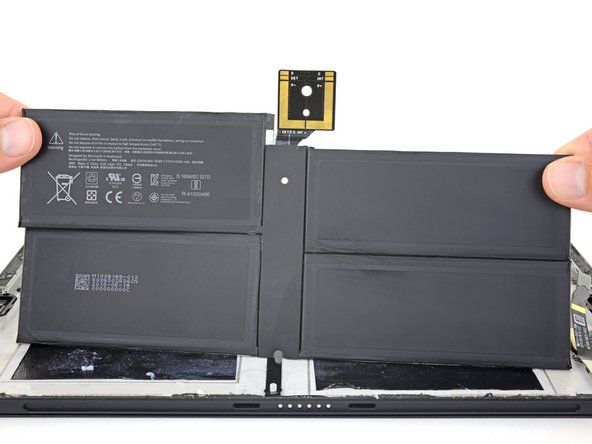
- Gently lift the battery out of the case.
- Do not reuse the battery after it has been removed, as doing so is a potential safety hazard. Replace it with a new battery.
- During reassembly, follow this guide to clean off old adhesive and apply new adhesive from a pre-cut adhesive card.