Lenovo ThinkPad X131e Disassembly
ID: 147185
Description: There is a lack of disassembly guides online...
Steps:
- Remove external battery by unlocking the safety latches near the external battery
- Move the safety latches from the "Locked" to "Unlocked"
- Remove the two 7 mm Phillips 1 screws from the top left and right corners.
- Two 7mm Phillips #1 screws
- Unscrew the 3 captive screws (they will NOT come out, once they unscrew and "click," they are out of their socket)
- Insert a plastic spudger and pry up the bottom cover from the laptop.
- Here you can access RAM, HDD, WiFi and WiFi modules.
- Remove the two 6 mm Phillips #1 screws holding down the HDD Cage
- Then pull the HDD plastic pull tab at a slight angle to unseat the HDD from the computer.
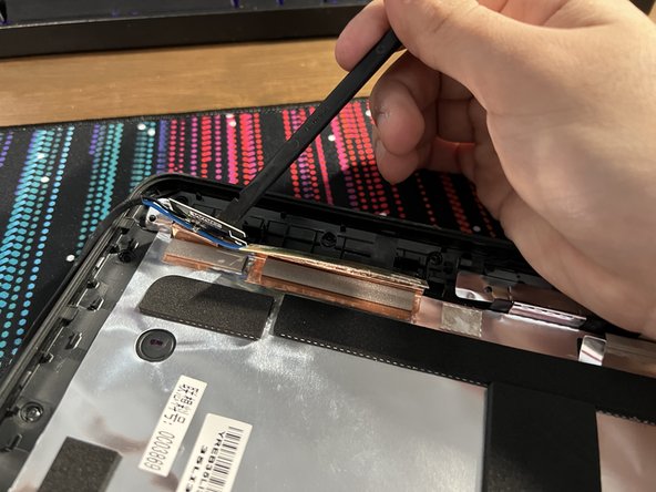
- Insert a plastic spudger underneath the antenna cable connections.
- Be careful and make sure to pry up evenly as the connector is small and fragile. It will pop out with relatively small effort if prying at the correct angle.
- Remove the two 4 mm Phillips #1 screws and then pull out the WiFi modules.
- Remove the four 9 mm Phillips #1 screws that are holding down the keyboard.
- Press both hands down firmly on the keyboard and slide forward to unseat the keyboard.
- Next lift and slightly pull out the keyboard.
- Be careful when lifting the keyboard as there are two ribbon cables attached to the main laptop which can tear easily.
- Unlatch the ribbon cables' retaining flap with a plastic spudger.
- Note: When reattaching the ribbon cables, they don't slide "in" to their connector, they lay on the pins, and what holds them down is their retaining flap.
- Make sure the pins are aligned with the ribbon cable when securing the retaining flap.
- Unscrew the three 5 mm Phillips #1 screws that are holding down the top cover.
- Use a plastic spudger to lift the lap on the trackpad's ribbon cable.
- Then carefully pull out the ribbon cable.
- With your fingers, grip the other exposed cable and carefully pull out horizontally to disconnect the connection.
- Insert a plastic spudger in between the top cover and frame of the laptop. Start prying, making your way around the whole laptop.
- Remember to make sure the two 7 mm screws from Step #2 have been removed or else the top cover will not come off.
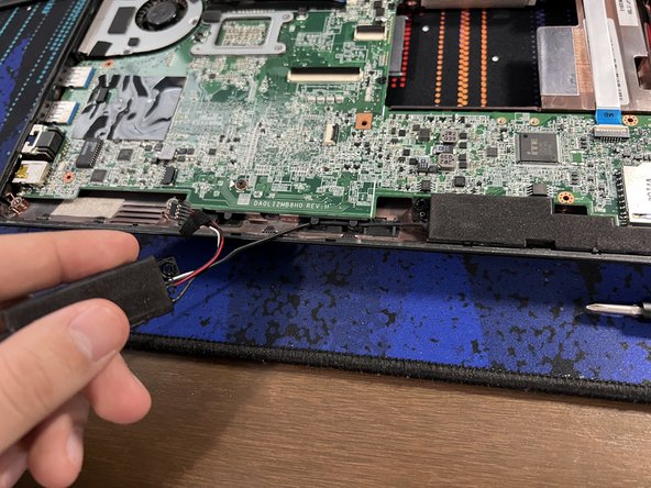
- Disconnect the speaker wire from the motherboard with your fingers or tweezers.
- Remove the four 6 mm Phillips #1 screws holding down the speakers near the bottom of the case.
- Pull out the two speakers and their wiring carefully.
- Remove the five 4 mm Phillips #1 screws.
- These can be identified by a small white arrow pointing towards their socket.
- Remove the two 6 mm Phillips #1 screws near the middle of the board.
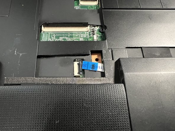
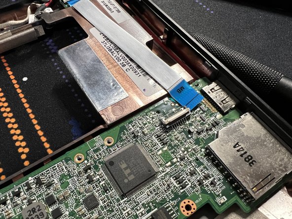
- Disconnect the safety latch near the bottom right with a plastic spudger and carefully remove the ribbon cable.
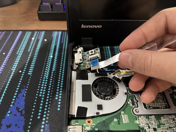
- Insert a plastic spudger to remove the safety latch of the top middle ribbon cable, then disconnect the ribbon cable.
- when the ribbon cable meets the fold, carefully peel the cable off as there is some adhesive holding it down in place.
- Disconnect the last visible cable by pushing it horizontally out with a plastic spudger.
- Remove the small boards on the top left and right of the laptop with either your hands or tweezers.
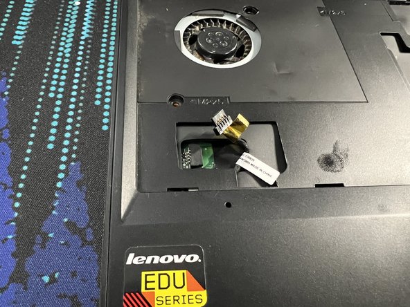
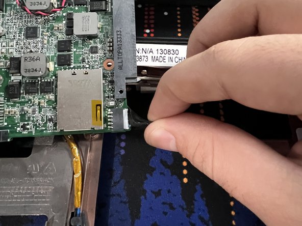
- Peel off from the right of the sticker, there will be a black plastic pull tab that is there.
- With your fingers, grip and pull the tab up vertically, with some force, the connector will disconnect.
- Insert plastic spudger from the left and slightly raise the motherboard.
- There are plastic pegs on the left side of the motherboard, insert another pry tool or a finger underneath from the right side of the motherboard and lift "up" a bit to free the motherboard from the pegs.
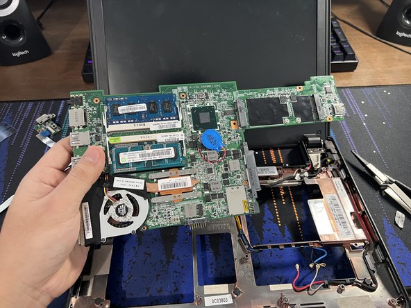
- After that, you can pull the motherboard away by pulling to the left.
- Flip the motherboard to its other side.
- Then pull out the charging cable by holding it with your fingers and "wiggling" it out.
- The motherboard is now free.
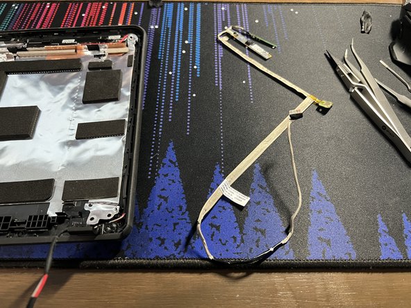
- Grab the black and blue antenna cables carefully pull them out of their path until they're no longer held down.
- Do the same thing with the gray and red antenna cables.
- Grab and remove the last cable from its place.
- Remove the four 6 mm Phillips #1 screws from the hinges.
- The display will now be free.
- Note: If you noticed any screws attached to my hinges, those are there because my computer's frame is broken, and I didn't want to lose the threading for the screws. If your frame isn't broken, then there won't be any screws left on the hinges.
- The charging port is held down with pressure
- Stick a plastic spudger on the bottom port of the charging port and pry up to remove the port.
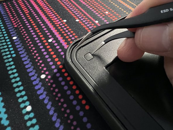
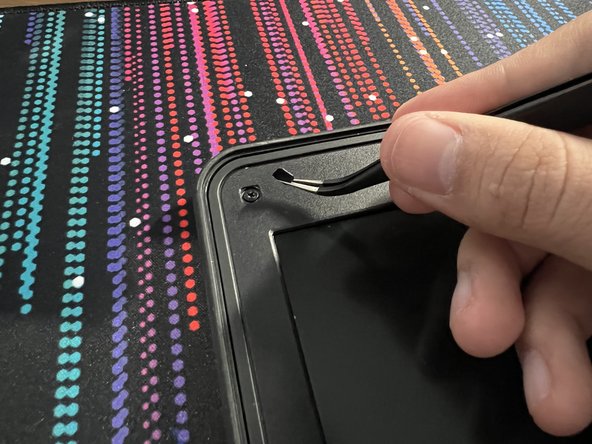
- Now that the display is free, insert a thin metal prying tool like tweezers or a needle to pry off the plastic screw covers in the four corners.
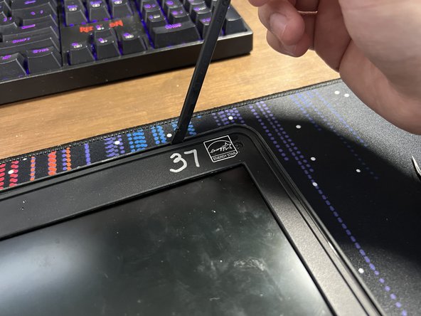
- Now insert a plastic spudger between the top of the assembly and the bezel and start prying.
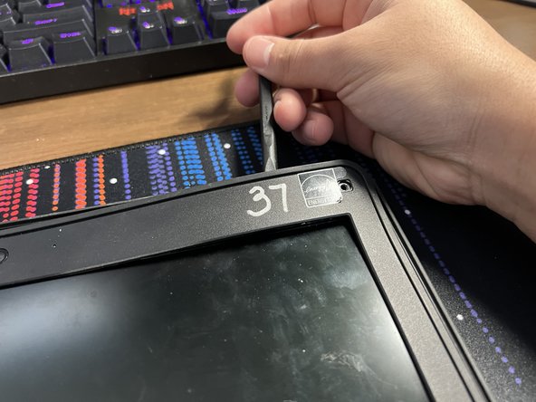
- Make your way around the bezel. You can also pry from the other side of the bezel by the screen with your finger to make it easier.
- Keep prying until the bezel is free.
- Remove the four 4 mm silver screws holding down the LCD panel.
- Lift and remove the silver shielded wire connected to the LCD panel out of the way.
- Use a plastic prying tool near the edge of the panel where the silver screws once were to lift up the LCD panel.
- The LCD panel is now free.
- Remove the two 6 mm screws holding down the two hinge assemblies.
- The hinges are no longer secured to the frame and can be lifted away.
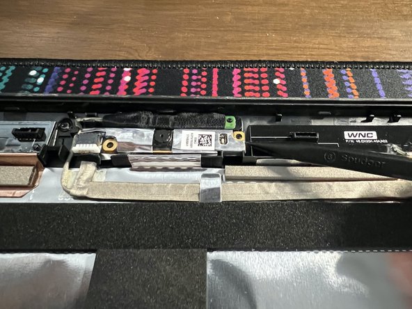
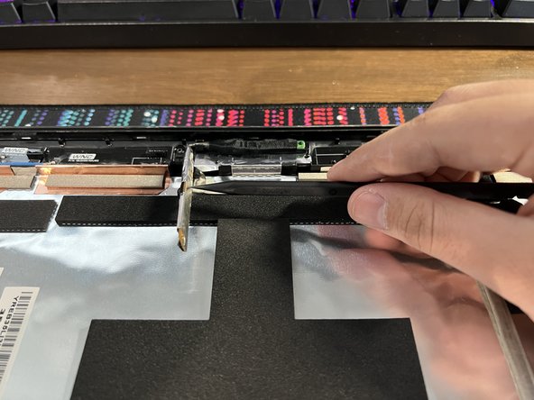
- The webcam and microphone are both attached to a silver shielded cable.
- The webcam assembly can be lifted away.
- There is black tape over the microphone that can be peeled off by tweezers, and then the microphones can be lifted away too.
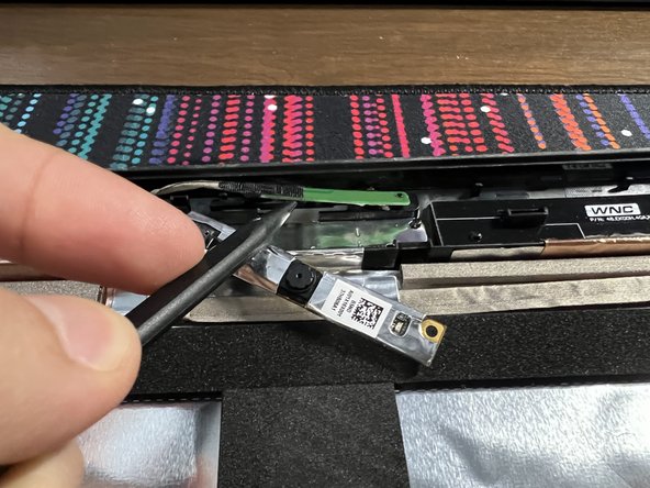
- Peel away the black cloth tape covering the microphone Printed Circuit Board (PCB)
- The microphone's PCB is glued down. Insert a plastic spudger from the left and make your way to the right to slowly release the microphone's PCB.
- With that, the microphone along with the webcam are now free.
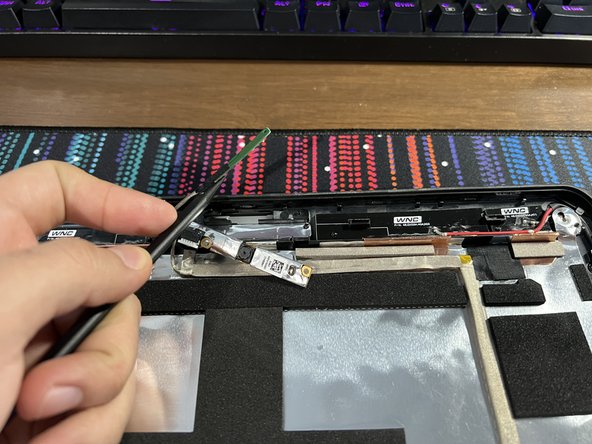
- Farther down the same shielded cable, there is more black cloth tape.
- Peel it away with some pliers.
- Because the small PCB is glued down with adhesive, insert a plastic spudger from the left, underneath the shielded cable, to pry it away.
- Carefully peel away the rest of the shielded cable.
- Make sure to remove the cable from its cable routing carefully when you get to the bottom.
- The cable is now free.
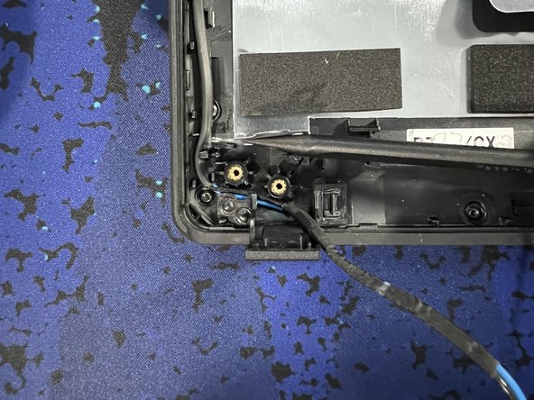
- Lift the cable shielding covering the cable routing for the WiFi and cellular antennas.
- Start removing the cable's from their routing slots.
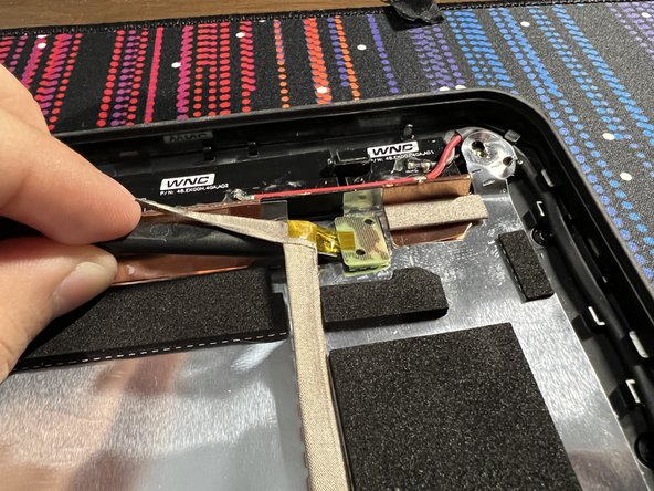
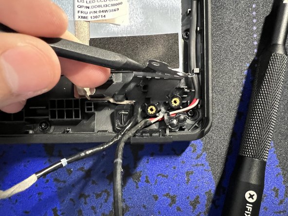
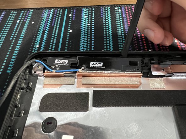
- Keep removing until you get to the top two black PCB's that the cables are attached to the frame.
- Insert a plastic spudger between the the PCB and the frame, and carefully pry up.
- The PCB should lift with relatively little effort.
- Now do the same with the other PCB.
- Peel away the PCB's and their attached copper tape carefully.
- Please see the next step if the silver shielding is peeling away with the copper tape.
- If the Silver Shielding starts to peel away with the copper tape, then insert a plastic pry tool from the bottom (other side) and start peeling from there.
- Now the silver shielding won't get damaged.
- Repeat steps 40-44 on the other side with the other antenna cable.
- The laptop is now fully disassembled. Thanks for reading my guide!