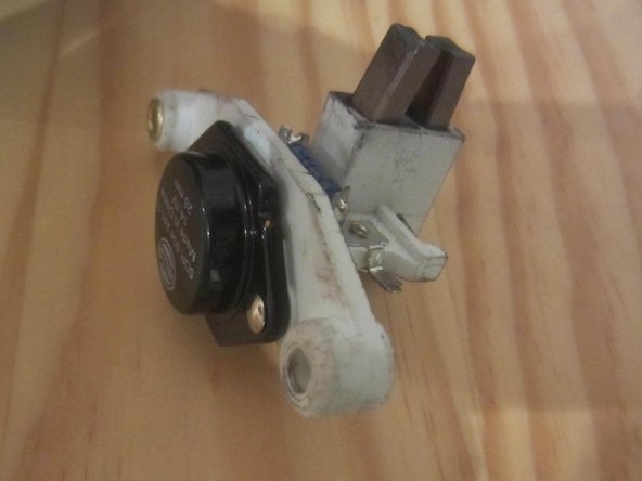
Bosch 70A alternator bearing, commutator contacts replacement
ID: 147213
Description: In order to overhaul the alternator with...
Steps:
- Remove the regulator: two screws (slotted in the original)
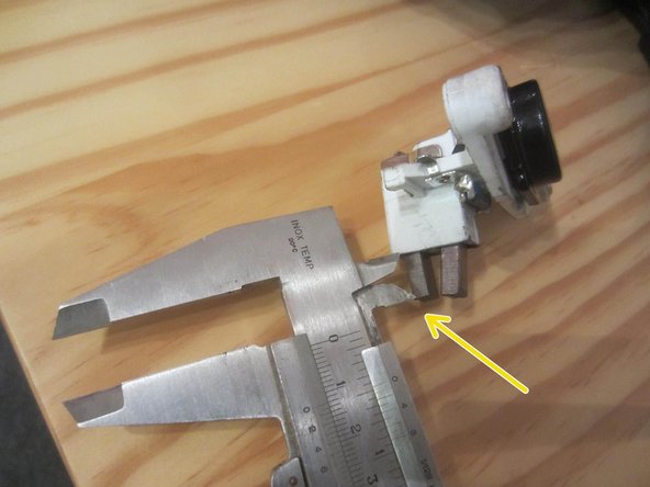
- The carbon brushes should still protrude by at least 5 mm, otherwise replace the carbon brushes or the entire regulator. Here they are 12 mm.
- On older alternators, the screws may be rusted solid. Spray generously with rust remover or penetrating oil and allow to soak in for a while if necessary.
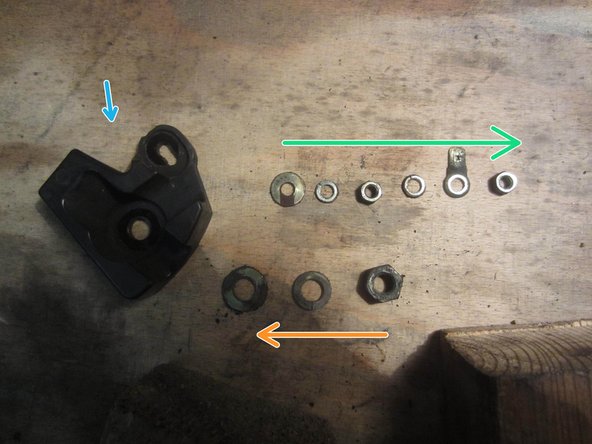
- Unscrew the nuts and washers (if present) on the two/four pull arms.
- Unscrew the nuts and washers on the positive contact bolt (13 mm).
- Unscrew the nuts, washers, and contact tongue from the control line (7 mm).
- Unscrew the nuts, washers, and contact tab from the control line (7 mm).
- Unscrew the belt pulley: hold it in place with an old belt and unscrew it with a wrench or ratchet. (22 mm)
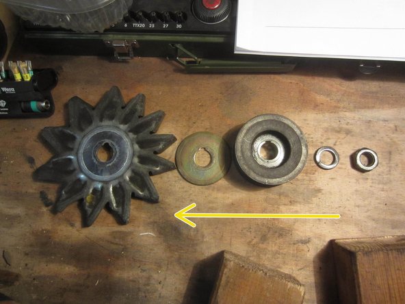
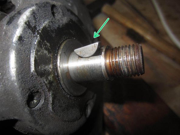
- Remove the nut and all washers as well as the fan blade, noting the order.
- Remove the crescent key.
- Mark the alternator housing for later reassembly.
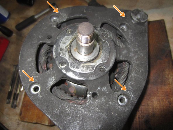
- If the four tie rods (screws) are of different lengths, note or mark where each one belongs
- Unscrew the four screws (PH2).
- Note: There are versions with four screws of the same length and versions with screws of different lengths.
- Pull out the front housing part with the stator, using a plastic hammer to help if necessary.
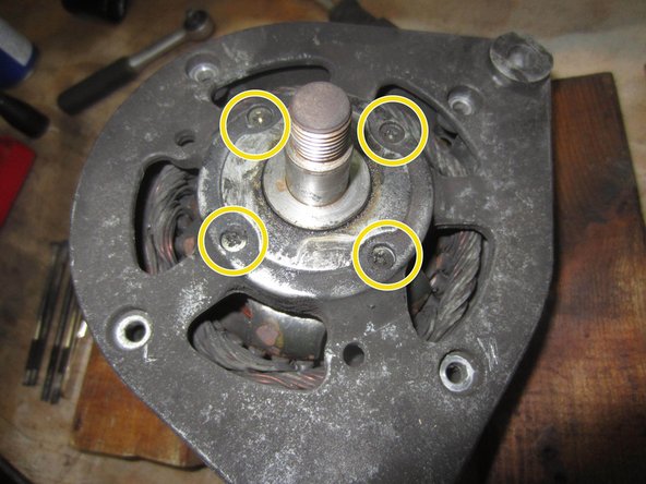
- Remove the four countersunk screws
- Pull the rotor out of the bearing shield (housing).
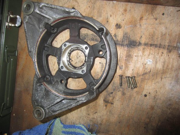
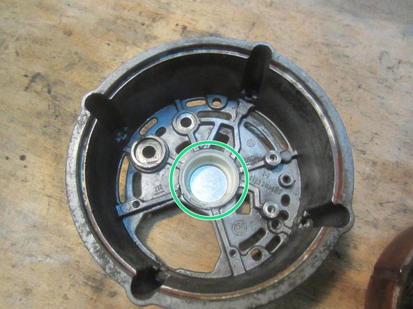
- Bearing shield and screws
- Check: between the commutator segments 2.8 ohms +/- 10%, no contact with the housing?
- Even if the resistance is correct, the contacts are so worn that the commutator ring must be replaced.
- Wear limit: commutator ring diameter 27.8 +/- 1 mm, max. runout 0.03 mm
- This step is also necessary to replace the commutator ring
- Remove the two bearings from the rotor shaft; a good bearing puller is helpful.
- This step is necessary to check the diodes
- In the rear housing, remove the two screws that connect the diode plate to the housing
- Pull the diode set and stator winding out of the housing
- Do not lose the plastic bushing (or sliding ring).
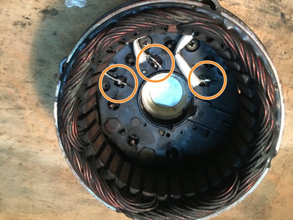
- Desolder the three stator cables.
- Do not break the cables (e.g. by bending them).
- Solder quickly (short and hot) so as not to fry the rectifier diodes.
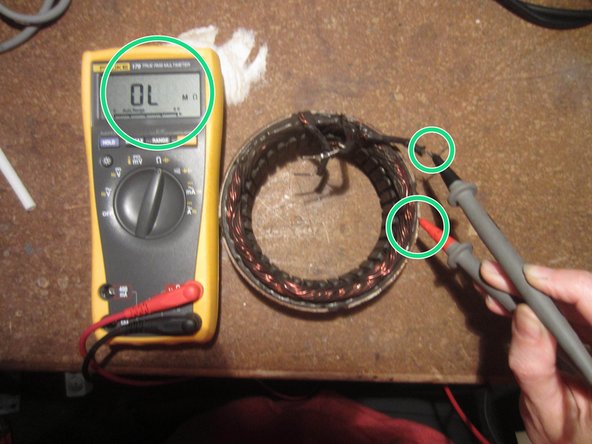
- Check the stator windings for short circuits to ground. Target: infinite resistance
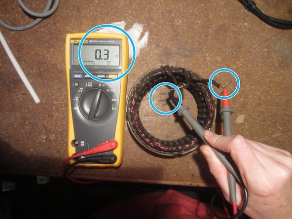
- Check continuity of the stator windings (the displayed 0.3 ohms) are inaccurate but continuity is present
- Theoretically, the resistance of the windings (always 2 phases) can also be checked: should be 0.09 ohms +/-10%. However, this is not possible with a simple multimeter; 0.3 ohms is displayed here.
- Insert translation here