Technics EAH-AZ40P-S Bluetooth Headphone Teardown
ID: 147458
Description: A look inside the Technics EAH-AZ40P-S...
Steps:
- Superior Call Quality with JustMyVoice™ using an Utterance Detection MEMS Microphone
- Ambient Sound Mode
- 6mm Driver units with PEEK diaphragm
- 7.5 Hours Playback
- Alexa Enabled
- Cheaper Bluetooth Ear Phones then the Technics AZ60 but still has utterance detection support
- What is in the box
- Headphones / Charging Case
- USB 'C' Cable
- Headphone rubber tips for various ear sizes
- User's Manual
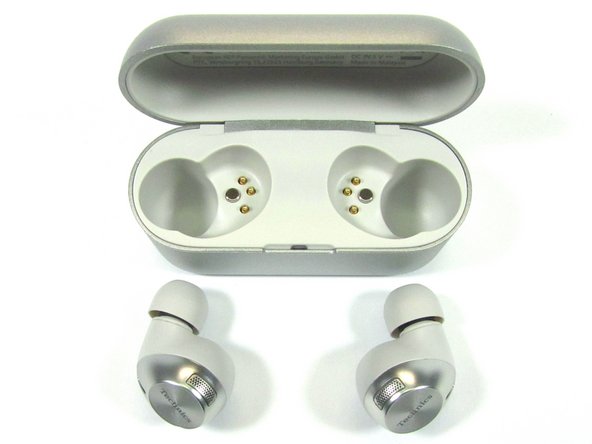
- Charging Case with headphones
- Close up view of headphones
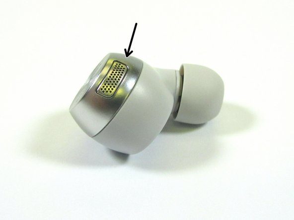
- Side View of the Headphones
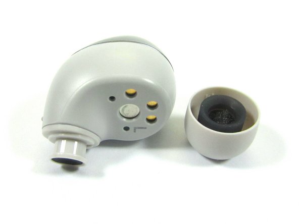
- USB D+ / D- Interface
- Power Connections
- Light Pipe for light based proximity Detector
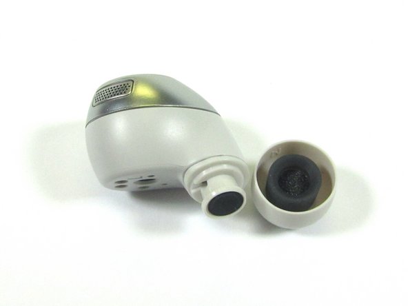
- Sound input
- Location inside for the Utterance Detector
- Speaker Sound Port
- MEMS Microphones are coupled behind these grids
- Views of the Headphone with the rubber ear piece removed
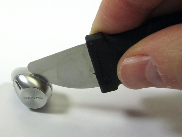
- The headphone touch sensor cap is glued onto the headphone. The only way in was to gently used a Xacto knife to break the glue seal
- Once a the touch sensor cap gave a little, a Jimmy Tool was used to pry the cap from the headphone body
- Since the headphone was easy to open, it may be possible to perform a battery change without damaging the headphone
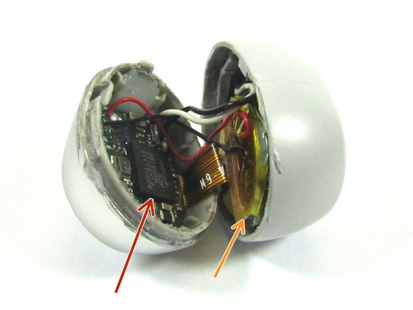
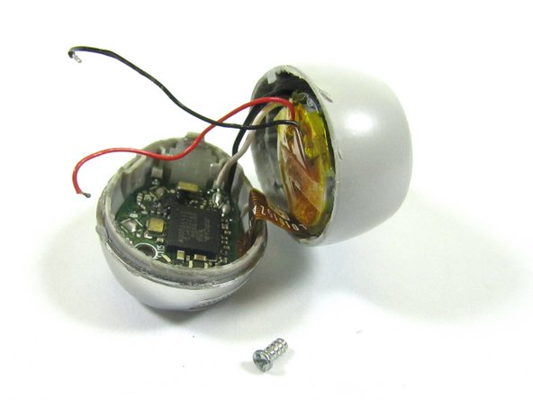
- Once the headphone was open, we get our first look at the inside of the headphone
- Bluetooth Radio / MCU
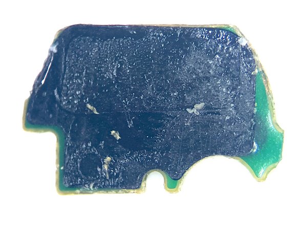
- Battery
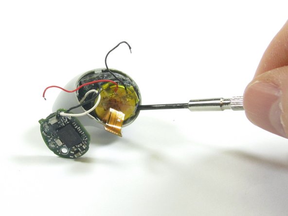
- Before removing the battery, it was unsoldered from the MCU PCB. This was safety measure, so the that the battery could not be accidentally shorted during the teardown. It is recommend to unsolder the battery in any teardown where it is soldered in and not easy to remove to reduce the change of problems
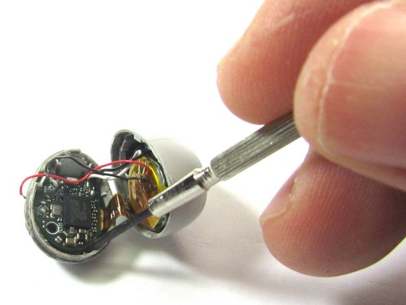
- The battery was pried out using a small flathead screw driver
- The battery is a Li-ion 3.7V / 0.2Wh or 3.7V / 54mAh
- Was not able to the the vendor of the battery. If you happen to know the battery vendor. Please leave it in the comments
- There is a a Phillips Head ##00 screw that holds the MCU board in place in the headphone
- Removing the MCU screw allows the MCU to be pried out with a small flathead screw driver
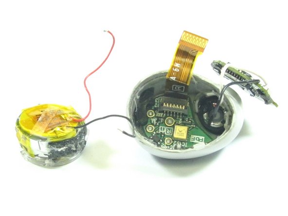
- With the MCU PCB removed, we can see the Touch Sensor and Bluetooth Antenna Interface Board
- MCU PCB
- Touch Sensor and Bluetooth Antenna
- Battery
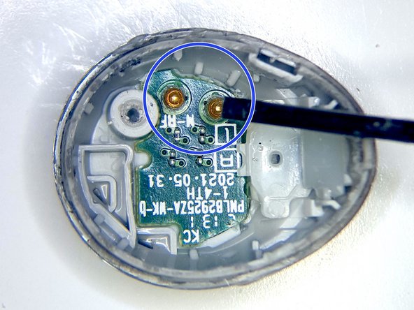
- The MCU PCB Interfaces to the Touch Sensor and Bluetooth Antenna via pogo pins
- The Touch Sensor and Bluetooth Antenna PCB was pried out with a flathead screw driver
- The Touch Sensor and Bluetooth Antenna PCB is held in place with double sided foam tape
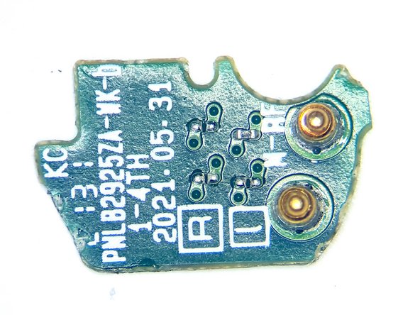
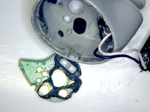
- Pulling off the double sided foam tape, we can see the Touch Sensor and Bluetooth Antenna structure
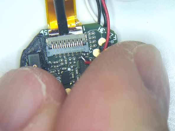
- To release the MCU PCB from the headphone, we can pop the retention clip interfacing the MCU to the headphone via the flex ribbon cable
- Pulling the flex cable from the retention chip frees up the MCU board, but the MCU PCB is still attached to the speaker
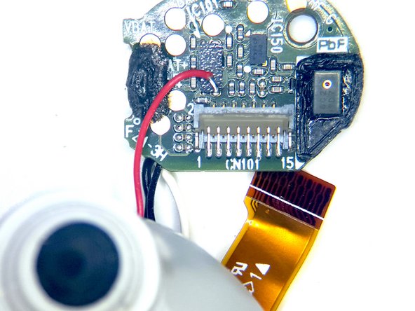
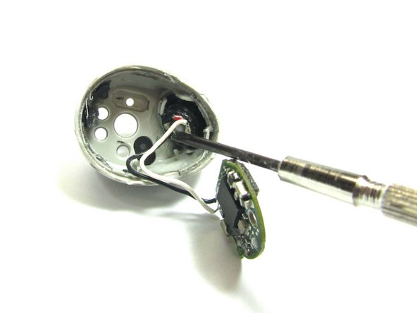
- Now, we pop of the other side of the flex cable from the retention chip, so that we can pry out the Power, USB, and Utterance Detection Microphone PCB
- This PCB is also held in place with double side foam tape
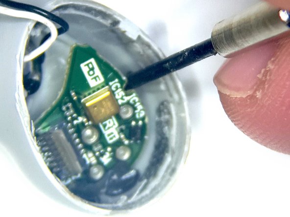
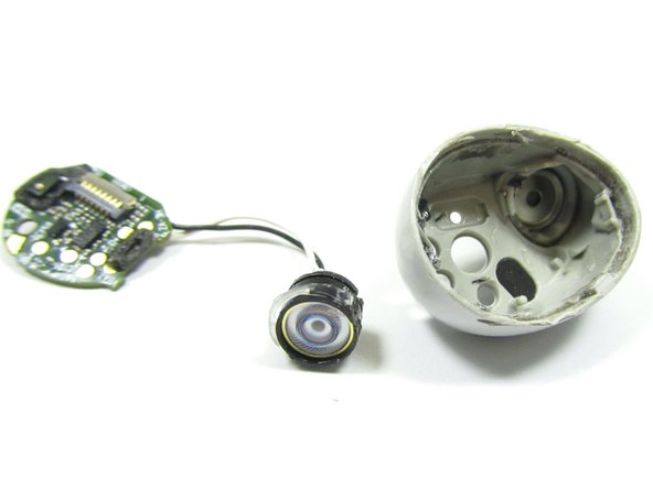
- Now we can remove the speaker from the headphone. The speaker is held in place with double side foam tape, so it best to use an Xacto knife to cut around the speaker. Then the speaker can be pried out with a small flathead screw driver
- Now with the headphone dissembled, we can turn our attention to looking at the components that make up the headphone. We will start with the MCU PCB
- AIROHA AB1565M - ARM Cortex M4/Bluetooth 5.2 Dual Mode with Active Noise Cancellation
- MEMS Microphone. Not able to cross the part. The part has the following markings: 2C4 1X7. If you happen to know the part, please the part information in the comments
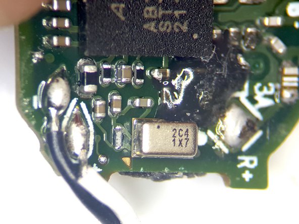
- Crystal Oscillator
- MEMS Microphone. Not able to cross the part. The part has the following markings: 6C2 1D7. If you happen to know the part, please leave the part information in the comments
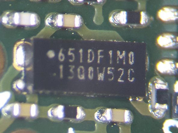
- Battery Management IC. Part Markings 651DE1M0 13Q0W52C
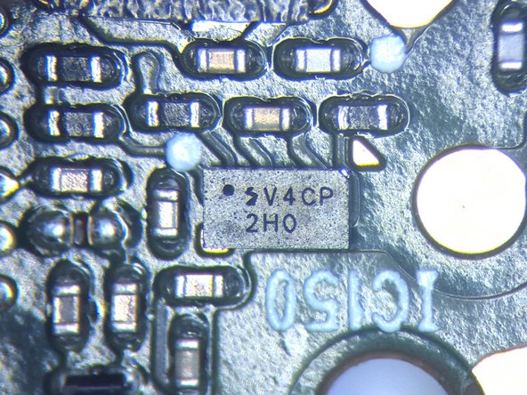
- Could not cross the part. The part has the following markings: SV4CP 2H0. If you happen to know the part, please leave the part information in the comments
- Close up view components on the Front Side of MCU PCB
- MCU with Bluetooth
- AIROHA AB1565M - ARM Cortex M4/Bluetooth 5.2 Dual Mode with Active Noise Cancellation
- Close up of the MEMS Microphone
- MEMS Microphone. Not able to cross the part. The part has the following markings: 2C4 1X7. If you happen to know the part, please the part information in the comments
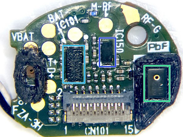
- Close up view of components on the Backside of MCU with Bluetooth
- MEMS Microphone
- Not able to cross the part. The part has the following markings: 6C2 1D7. If you happen to know the part, please leave the part information in the comments
- Battery Management IC
- Part Markings 651DE1M0 13Q0W52C
- Could not cross the part. The part has the following markings: SV4CP 2H0. If you happen to know the part, please leave the part information in the comments
- We can not turn our attention to the Power, USB, and Utterance Detection Microphone PCB
- The part number on this component was not readable, but it location near the power interface may mean that it is either a Diode or PMOS FET
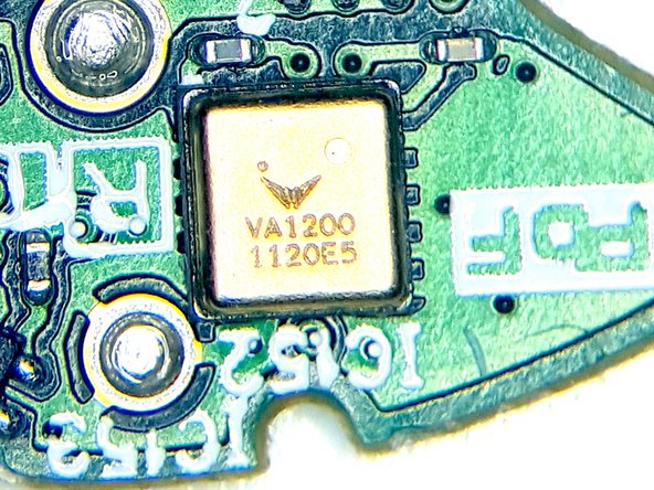
- Vesper VA1200 - Analog Piezoelectric MEMS Voice Accelerometer. Bone Sensor - used for Utterance Detection
- Light based Proximity Detector. Detects when the microphone is in the ear canal or in the charger
- Close up view components on the Front Side of Power, USB, and Utterance Detector PCB
- The part number on this component was not readable, but it location near the power interface may mean that it is either a Diode or PMOS FET
- Vesper VA1200 - Analog Piezoelectric MEMS Voice Accelerometer. Bone Sensor - used for Utterance Detection
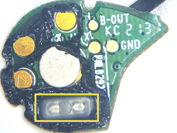
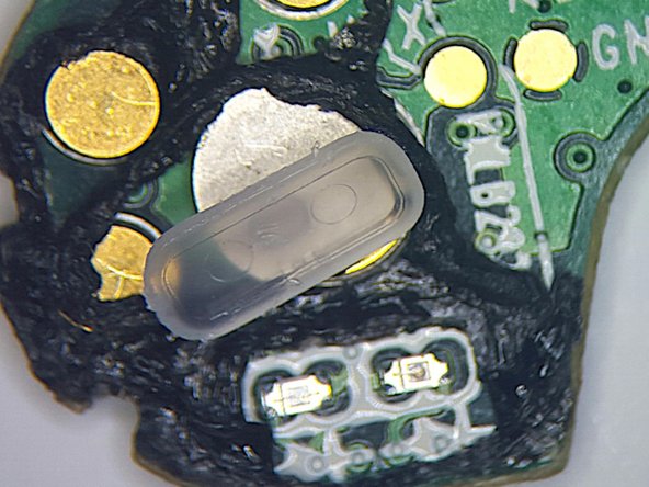
- Close up view components on the Backside of the Power, USB, and Utterance Detector PCB
- Light based Proximity Detector. Detects when the microphone is in the ear canal or in the charger
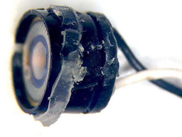
- Light based Proximity Detector with cover removed. The Transmit and Receiver LEDs can be seen.
- Close up view of the front and the side of 6mm Driver (speaker) with PEEK diaphragm
- No part number found on component. If you happen to know the component please leave the component information in the comments.
- Close up view the Microphone interfaces to the topside [Touch Sensor / Antenna Cap]
- MEMS Microphone Interface
- MEMS Microphone Interface
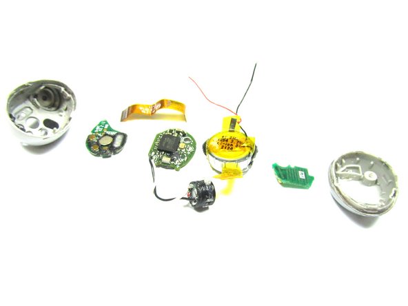
- Teardown Exploded Top Side and Backside views of the Headphone
- This teardown showed that with little effort the batteries in the headphone could be changed out.