Steam Deck Speakers Replacement
ID: 148991
Description: Use this guide to replace the speakers in your...
Steps:
- Turn on your Steam Deck and allow the battery to discharge below 25% before starting your repairs, as a charged lithium-ion polymer battery can be dangerous if accidentally punctured.
- As an extra precaution, Valve recommends putting your Steam Deck into battery storage mode within the BIOS before starting any internal repairs. Read how to do that here.
- Power down your Steam Deck and unplug any cables.
- If you have a microSD card installed, make sure to remove it before opening the Steam Deck. If you attempt to remove the back cover with it still installed, it could snap right in half.
- During your repair, it can be helpful at times to lay the Steam Deck face-down into its case to protect the thumbsticks and prevent wobble.
- Use a Phillips driver to remove the eight screws securing the back cover:
- Four coarse thread 9.5 mm-long screws
- Four fine thread 5.8 mm-long screws
- Despite the standards, Phillips screwdrivers can vary in size and shape—two drivers labeled as the same size may fit differently in the same screw. Use the size that fits the snuggest into the screw head.
- Throughout this repair, keep track of each screw and make sure it goes back exactly where it came from to avoid damaging your Steam Deck.
- Insert an opening pick into the thin gap between the back cover and the front shell, along the edge of the right grip.
- If you're having trouble inserting your pick at the grip seam, try starting at either the top or bottom long edges first, then slide the pick towards the grip.
- Pry up on the back cover to release it from the locking clips.
- Once the clips are disconnected from one edge, the rest disconnect easily.
- Grip the back cover at the opening you just created and pull it up and away from the device to unclip the long edges.
- Remove the back cover.
- If you have a refreshed Steam Deck version with the black motherboard cover, skip this step.
- Use a pair of tweezers to remove the piece of foil tape covering the hidden screw on the board shield.
- If possible, try not to rip or tear this tape so it can be reused. If necessary, you can fashion a replacement by cutting a piece of aluminum foil tape to fit.
- Use a Phillips driver to remove the three screws securing the board shield:
- One 3.4 mm screw
- Two 3.7 mm screws
- Only the two 3.7 mm screws along the left edge are present in refreshed Steam Decks.
- Remove the board shield.
- Depending on the age of your Steam Deck, this shield may stick to the thermal pads underneath.
- During reassembly, ensure that the fan cable lays on the side of the board shield and isn't pinched underneath.
- Grip the battery cable by its pull tab and pull it directly away from the motherboard to disconnect it.
- Alternatively, use the flat end of a spudger or a clean fingernail to gently push the connector out of its socket, then disconnect it completely by hand.
- Use a Phillips driver to remove the 3.4 mm screw securing the SSD.
- With the SSD screw removed, the SSD will pop up at a shallow angle.
- Grip the end of the SSD and pull it away from its M.2 board connector to remove it.
- During reassembly, insert the SSD at a shallow angle into its board connector, and secure it back into its horizontal position with the SSD screw.
- Use a pair of tweezers to remove the sticker from the top edge of the fan.
- If possible, try not to rip or tear this sticker so it can be reused. Use a little bit of heat if necessary to soften the adhesive.
- If the sticker feels like it might tear, use tweezers to peel up one edge just until you can grip it with your fingers, then remove the rest by hand.
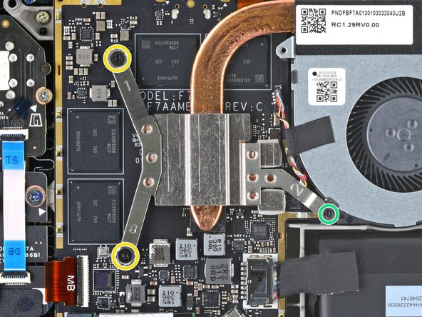
- For original Steam Decks: Use a Phillips driver to loosen and remove the two screws securing the heatsink to the motherboard:
- One captive 3.5 mm screw
- One 3.4 mm screw
- No, your eyes don't deceive you! The third heatsink screw was removed earlier in the disassembly: it doubles as the hidden board shield screw.
- For refreshed Steam Decks: Use a Phillips driver to remove the three screws securing the heatsink to the motherboard:
- Two 2.9 mm screws
- One 3.7 mm screw
- During reassembly on both versions, tighten these screws in order (1, 2, 3) as stamped into the heatsink.
- Lift and remove the heatsink.
- Before reinstalling the heatsink, follow this guide to clean the heatsink and APU and reapply thermal paste.
- Use a pair of tweezers to grip the edges of the fan connector and pull up to disconnect it from the motherboard.
- Pull the fan cable by its connector, not the wires themselves.
- Use a pair of tweezers to peel up and remove the Wi-Fi shield tape.
- If possible, try not to rip or tear this sticker so it can be reused. Use a little bit of heat if necessary to soften the adhesive.
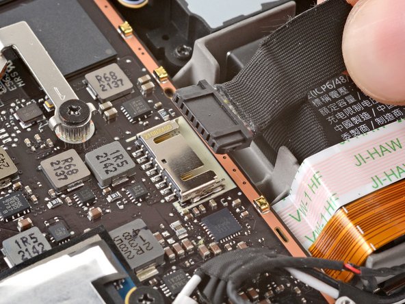
- Use a pair of tweezers to grip the edges of the speaker connector and pull up to disconnect it from the motherboard.
- Pull the speaker cable by its connector, not the wires themselves.
- The Wi-Fi module is located next to the SSD on refreshed Steam Decks.
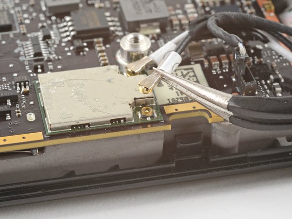
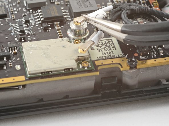
- Use a pair of tweezers to grip the antenna connector close to its base.
- Pull straight up to disconnect the cable.
- Repeat for the second antenna cable.
- During reassembly, ensure that both antenna cables are reconnected at their appropriate connectors. The labels on the cables match the markings on the Wi-Fi module.
- To reconnect each cable, align the connector directly over its socket, and then press down so it snaps into place.
- Use the pointed end of a spudger to lift up the small locking flap on the display cable's ZIF connector.
- Use a pair of tweezers to slide the cable out of its connector.
- Grip the cable by the pull tab, not by the cable itself.
- Refreshed Steam Decks don't have this audio cable. If you have a refreshed version, skip the next three steps.
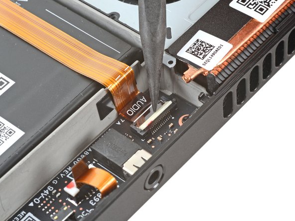
- Use the pointed end of a spudger to lift up the small locking flap on the audio cable's ZIF connector.
- Use a pair of tweezers to slide the cable out of its connector.
- Grip the cable by its pull tab, not by the cable itself.
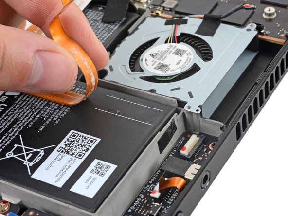
- Carefully peel the audio cable off of the battery.
- The audio cable is secured to the battery with some light adhesive.
- If the adhesive is stubborn, don't force the cable. Lightly heat the audio cable using an iOpener or a hair dryer to soften the adhesive.
- Use the pointed end of a spudger to lift up the small locking flap on the button board cable's ZIF connector.
- Use a pair of tweezers to slide the cable out of its connector.
- Grip the cable by the blue pull tab, not by the cable itself.
- Use a Phillips driver to remove the three 3.7 mm screws securing the motherboard.
- Remove the motherboard.
- The audio and button board cables attach to the underside of the motherboard with ZIF connectors.
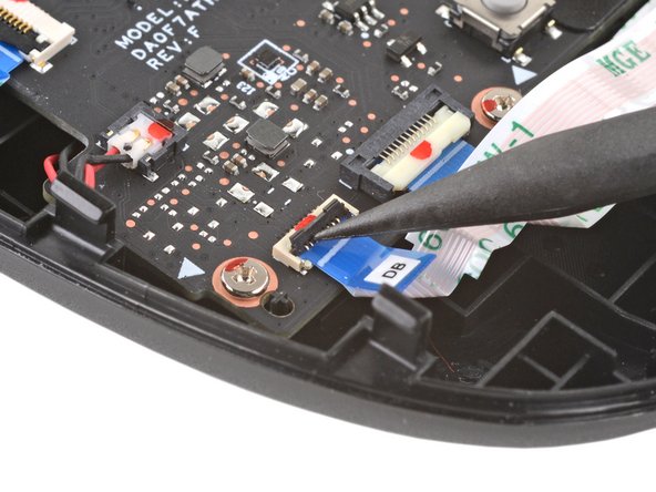
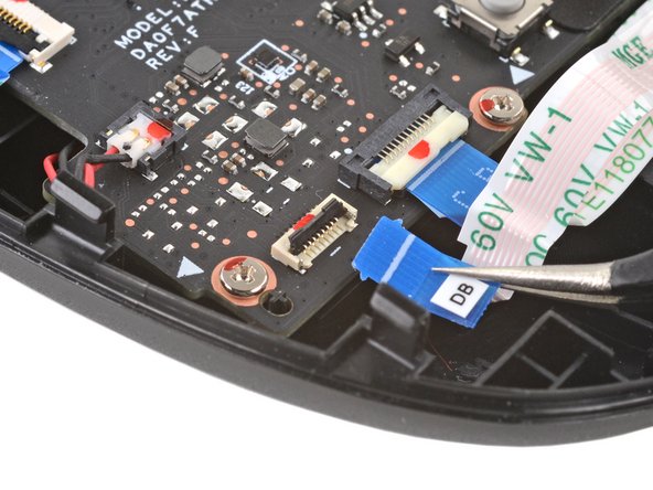
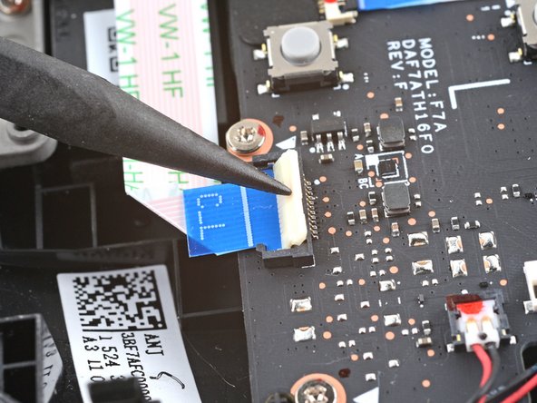
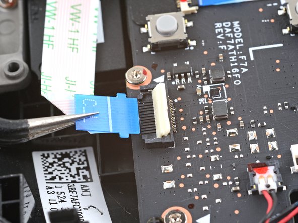
- Use the pointed end of a spudger to lift up the small locking flap on the button board interconnect cable's ZIF connector on the left button board.
- Use a pair of tweezers to slide the cable out of its connector.
- Grip the cable by the blue pull tab, not by the cable itself.
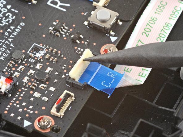
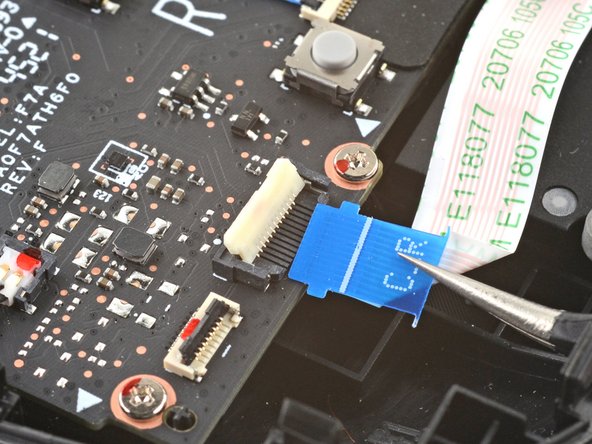
- Use the pointed end of a spudger to lift up the small locking flap on the button board interconnect cable's ZIF connector on the right button board.
- Use a pair of tweezers to slide the cable out of its connector.
- Grip the cable by the blue pull tab, not by the cable itself.
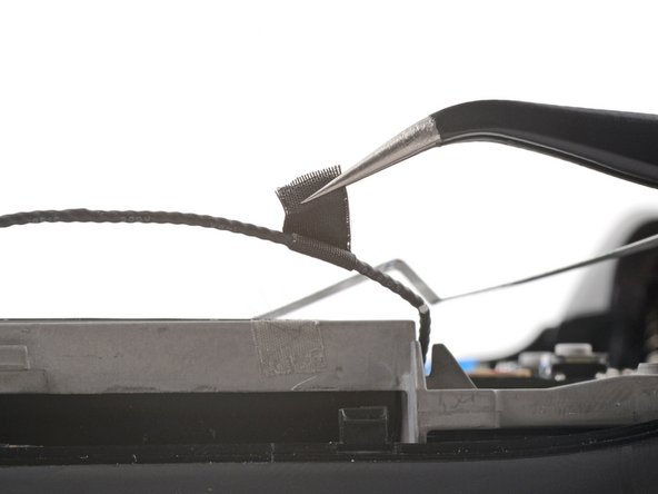
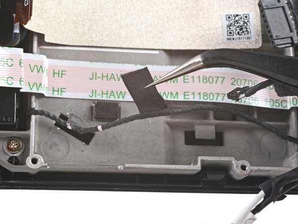
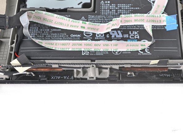
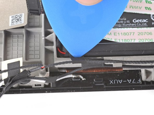
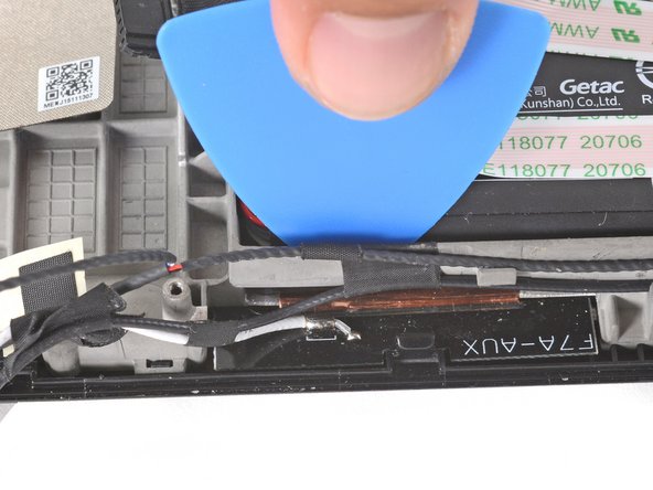
- Use a pair of tweezers to peel up the tape bundling the speaker wire to the Wi-Fi antenna cables.
- Use a pair of tweezers to peel up the various strips of black tape routing the speaker wire along the bottom edge of the chassis.
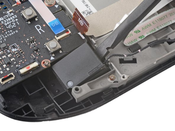
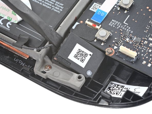
- Insert the flat end of a spudger between the right speaker and the frame.
- Pivot the spudger up to separate the speaker from the light adhesive securing it against the front shell.
- If the adhesive is stubborn, don't force the speaker out. Lightly heat it using an iOpener or a hair dryer to soften the adhesive underneath.
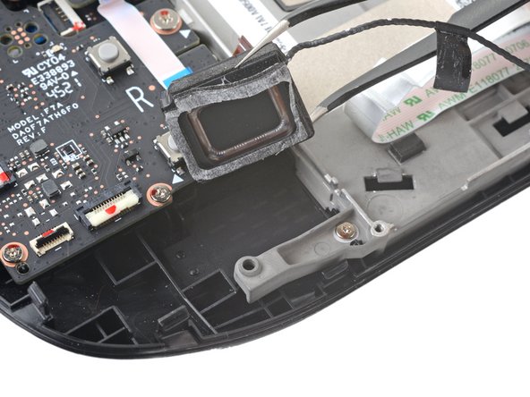
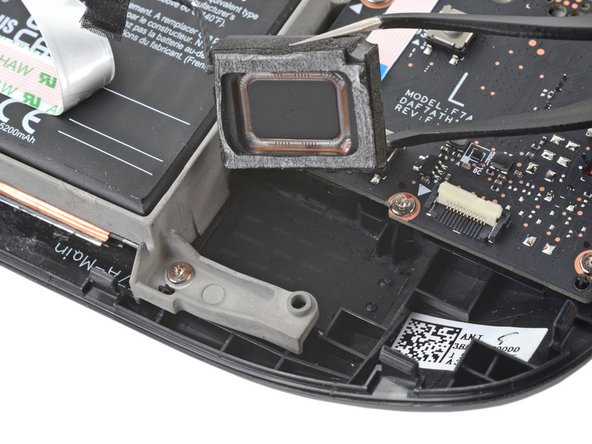
- Use a pair of tweezers to grip and remove the right speaker from its cavity.
- When removing the speaker, ensure that the fragile speaker mesh underneath stays in place. During reassembly, make sure it's uncreased and lays flat against the front shell.
- Insert the flat end of a spudger between the left speaker and the frame.
- Pivot the spudger up to separate the speaker from the light adhesive securing it against the front shell.
- If the adhesive is stubborn, don't force the speaker out. Lightly heat it using an iOpener or a hair dryer to soften the adhesive underneath.
- Use a pair of tweezers to grip and remove the left speaker from its cavity.
- When removing the speaker, ensure that the fragile speaker mesh underneath stays in place. During reassembly, make sure it's uncreased and lays flat against the front shell.
- Remove the tethered right and left speakers.
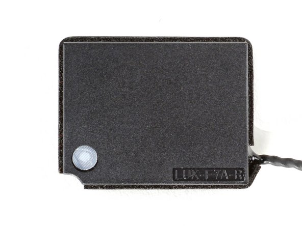
- During reassembly, note that the speakers are labeled, such as:
- LUX-F7A-L for the left speaker.
- LUX-F7A-R for the right speaker.
- To ensure a good adhesive bond, thoroughly clean all adhesion surfaces.
- Use adhesive remover or isopropyl alcohol (>90%) to remove any remaining residue. Wipe with a cotton swab or microfiber cloth until all the adhesive residue is gone.
- While isopropyl alcohol is generally safe to use on electronics, they will dissolve certain foam adhesives. Be careful to contain the alcohol when cleaning—don't use too much.
- Allow any leftover isopropyl alcohol to completely evaporate before reassembly.
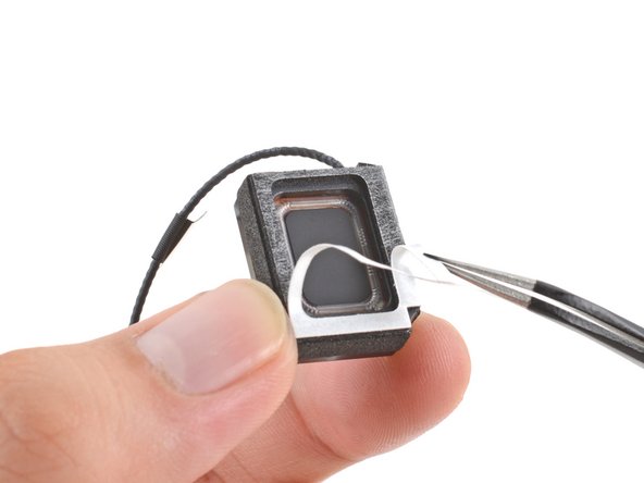
- Peel off and discard the liners on the speakers themselves, exposing the adhesive underneath.
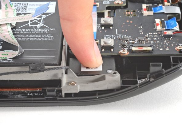
- Place each speaker into its slot and press firmly with your fingers to set them in place.
- The right speaker will be on your lefthand side and vice versa when working on the Steam Deck, as it's laying upside down.
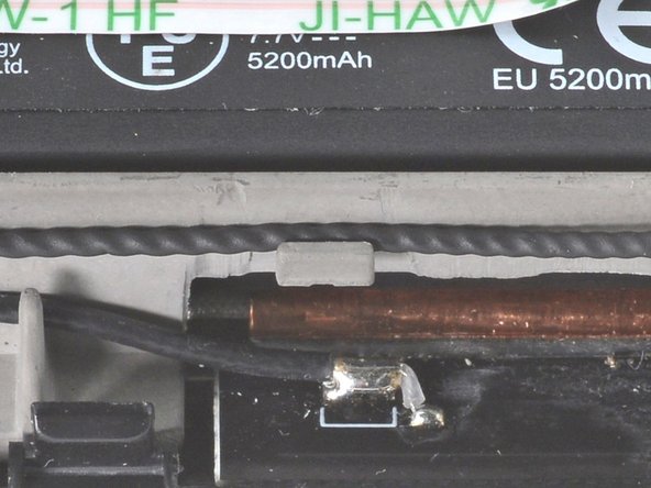
- Fit the speaker cable into the two hooks along the bottom of the chassis.
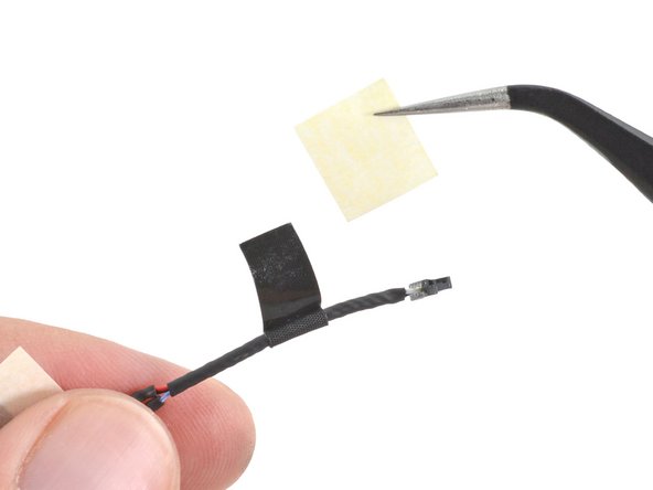
- Remove the adhesive liners from the tape strips along the speaker cable.
- To ensure proper cable management, stick one speaker cable adhesive to the top edge of the chassis, leaving ~3 mm at the top unstuck.
- Use an opening pick to wrap the adhesive over the edge of the battery tray, sticking it to the inside edge.
- Repeat for the second cable adhesive, and continue reassembly.