Chevrolet SS Sedan Rear Shock Absorber Replacement
ID: 149242
Description: This guide applies to 2015-2017 model cars...
Steps:
- With the vehicle parked on a flat surface, engage the parking brake
- Make sure the park light illuminates on the dashboard.
- As an extra safety measure, block the wheel on the opposite side from where you're lifting the car
- If removing the wheel, break the nuts before lifting the car with a breaker bar and 22mm or 7/8" socket.
- If your car was equipped with a spare tire kit, you can use that wrench too.
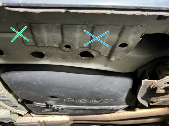
- When lifting the car, DO NOT use a jack on the pinch welds. Instead, use the plate on the frame rails as shown.
- When lifting with a jack and supporting with a jackstand:
- Place the jack here
- Place the jack stand here
- I like to place towels or something else soft between the jack / stands and the car to protect the paint
- Lift the car with the jack until you have the wheel a few inches off the ground. Then insert the jack stand and lower the car onto it.
- The jack SHOULD NOT be supporting the weight of the car while you're working under it.
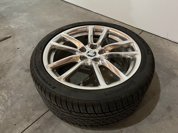
- If removing the rear wheel, fully loosen the lugs and set the wheel aside
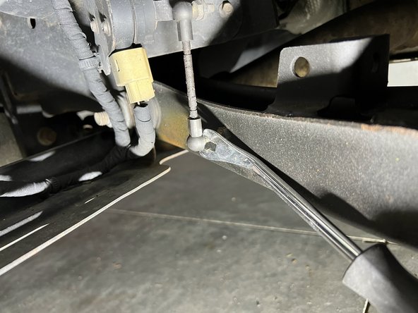
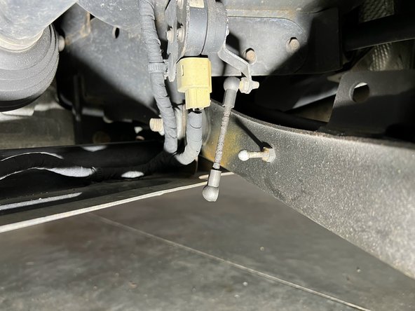
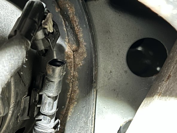
- There's a small arm linking the lower control arm to a vehicle height sensor.
- Separate the link from the lower control arm
- It takes a little force to pop the linkage off, a flat head screwdriver or trim removal tool can make the process easier.
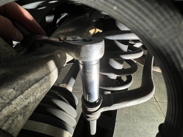
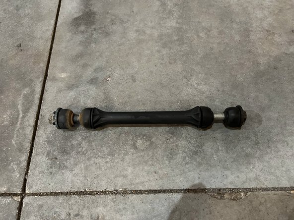
- Using a 15mm wrench and socket, remove the stabilizer bar link
- The brake line runs near the top of this link, to avoid damaging it you should hold the top nut with a wrench and turn the bolt from the bottom. Picture #2 is incorrect, the ratchet should be on the bottom!
- Pressure from the suspension may keep the middle plastic "grommet" section in place, you can wiggle it out or wait until the lower control arm is fully freed to remove it.
- When reassembling, torque this to around 30ft-lbs.
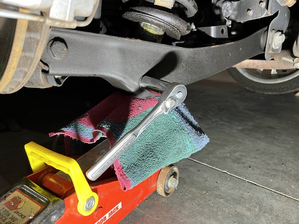
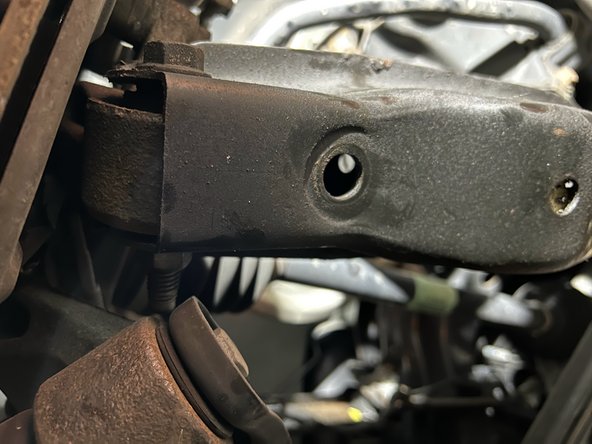
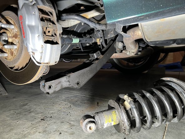
- A single 18mm nut and bolt secures the strut assembly to the lower control arm
- Remove the nut with a ratchet while holding the other side with wrench
- When re-assembling, this should be torqued to about 60ft-lbs, then tightened an additional quarter turn.
- If you cannot get the bolt out, use a jack to lift the lower control arm such that there is no force on the bolt. A small hammer can be used to tap the bolt out, but be careful not to damage the threads!
- When re-assembling, the jack will be necessary to align the control arm and strut to re-install the nut and bolt.
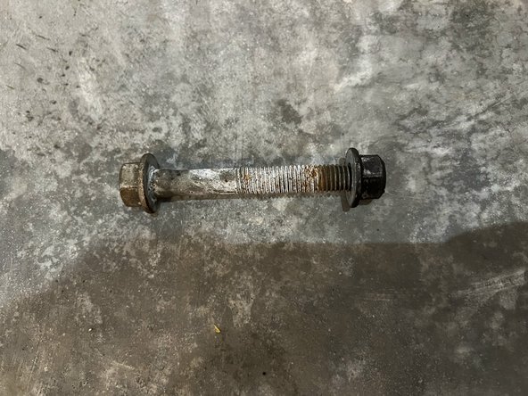
- An 18mm nut and bolt secures the lower control arm to the rear knuckle and must be removed.
- Like the strut-to-LCA bolt, this may require "finessing" the lower control arm with a jack to remove.
- When reassembling, torque this to around 35ft-lbs. You will need to do some prying with a pry-bar or large screwdriver in concert with a jack to get this realigned so you can re-insert the bolt.
- This nut is identical to the one removed in the previous step, but the bolt is shorter. Don't mix them up!
- After this step, the lower control arm should move freely.
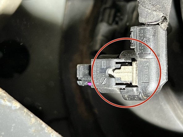
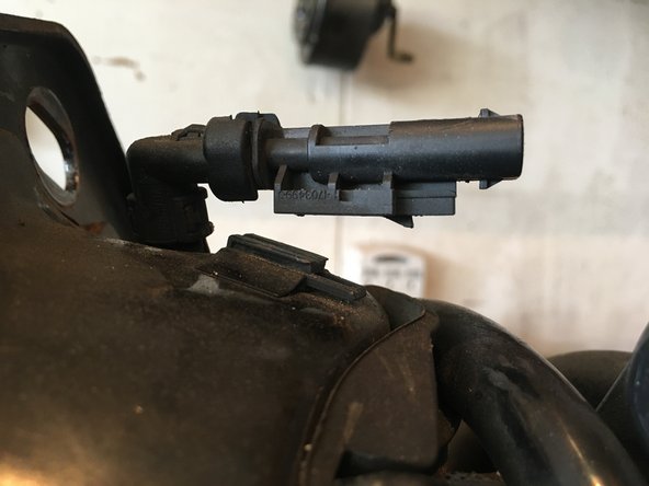
- The strut is electrically connected to the car via a 2-pin connector near where the strut mounts to the body.
- There's a small tab on the connector which you must depress to get it disconnected.
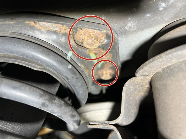
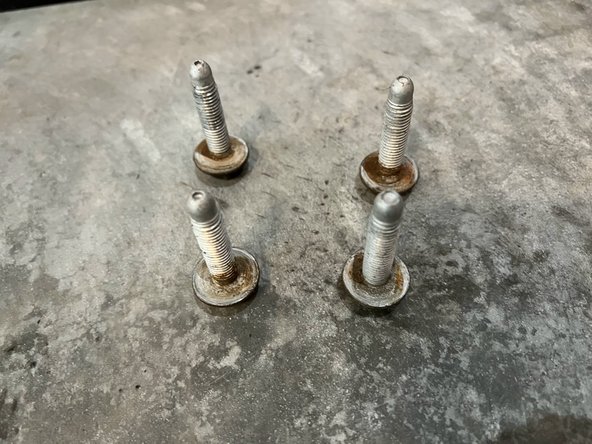
- Four 15mm bolts attach the strut to the body of the vehicle.
- These bolts seem to have gotten pretty rusty despite my car not being driven in a salty environment, it may be wise to replace them when replacing the strut.
- Remove the bolts, the strut should come free from the body.
- When re-assembling, these bolts should be torqued to around 45ft-lbs.
- You should be able to slide the strut out with the lower control arm depressed.
- The order that I've found which makes re-assembly the easiest is:
- Install the strut-to-LCA nut/bolt, but keep them loose.
- Install the strut-to-body bolts, but keep them loose
- Install the LCA-to-knuckle nut/bolt, with the help of a jack and prybar. This step is probably the most difficult.
- Get all nuts/bolts tightened snugly.
- Raise the LCA with the jack to "simulate" the car sitting on the ground, compressing the suspension. Then, torque everything to specifications.
- Move the strut assembly to a workbench, organization is important for this process because there are many parts in the strut assembly. It must be re-assembled in the correct order!
- The 2-pin connector at the top of the strut assembly slides into a grove, slide it out!
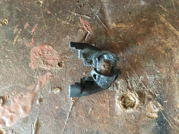
- There's an angled shell which wraps around the base of the connector, press on plastic tabs to remove it from the connector and set it aside.
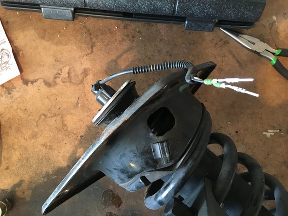
- You may have noticed that the electrical connector is larger than the hole at the top of the strut, it can't be slid through!
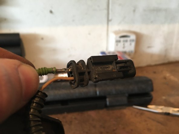
- The pins must be removed from the connector housing, this process requires some finesse.
- Make a "depinning tool" with a standard sized paperclip by bending it as shown
- Straighten most of the paperclip, but bend the end slightly
- This will be used to release the pins from the connector housing
- To release the pins from the connector, press the paperclip into the purple holes adjacent to each pin
- While pressing the paperclip into the hole, gently pull the wire from the back of the connector while wiggling the paperclip
- It shouldn't take much force to remove the pins when you correctly align the paperclip, do not force this apart because you can break the connector or wire!
- Pay attention to how the pins sit in the housing, the pin must align with the connector housing when reassembled
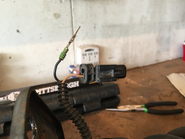
- With both pins removed from the connector, you can slide them through the top part of the strut.
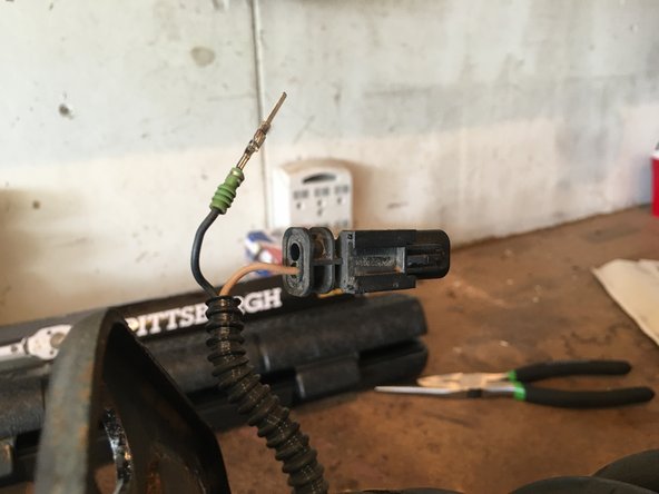
- The orientation of the colored wires in the connector is different on the driver and passenger side struts.
- The first image shows the driver side pinout with one of the wires partially removed
- The second image shows the passenger side pinout with one of the wires removed
- Look closely at the connector shell orientation in both pictures, as well as the orientation of the black / orange wire.
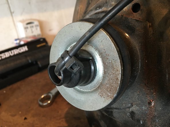
- A zip tie holds the cable to a plastic ring at the top of the shock, cut it
- Remove the plastic ring / aligner and put it somewhere safe
- Using MacPherson strut compressors, compress the spring slightly.
- You only need to compress the strut by around half an inch, just enough to allow further disassembly.
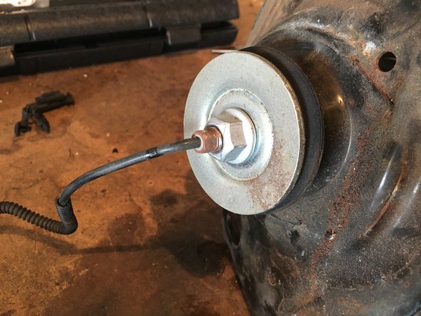
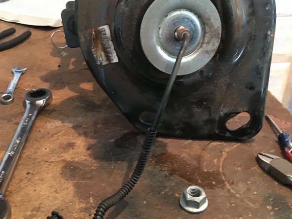
- Hold the center shaft of the strut with a 3/8" wrench while removing the nut at the top of the strut with an 18mm wrench.
- Slide the nut over the cable and remove it
- When reassembling, torque the nut to around 35ft-lbs.
- If you don't have an open-ended 18mm socket, get a good feel for the torque when you remove the nut so you can reassemble similarly.
- Remove the top washer, mounting plate/bushing, lower washer, and dust cap, keeping track of the order you removed them.
- The removable components are shown left-to-right in the order they go onto the strut.
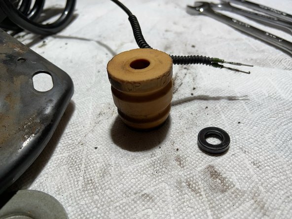
- Remove the small black washer and the yellow spacer.
- The top of the spacer is labeled
- You should now be able to slide the shock absorber out of the spring.
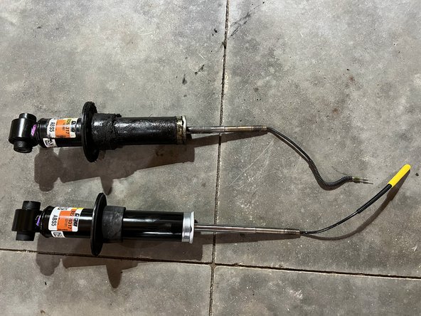
- This shock absorber shows all the symptoms of failure, it's coated in oily ferrofluid and grime.
- The new one is nice and clean!