Adjusting iRobot Braava Jet 240 magnetic contact sensors
ID: 149333
Description: If your Braava Jet 240 is behaving erratically,...
Steps:
- Turn the device off.
- Use your fingers to gently pop out the battery.
- Lift up the handle to reveal the eject button.
- Use your finger to push the eject button forward.
- Tilt the robot on its side and let the mop pad slide out.
- Remove the two 22.0 mm screws on the bottom-front of the robot using a Phillips #1 screwdriver.
- Use a Phillips #1 screwdriver and an iFixit opening tool to remove the two 15.0 mm screws on the front sides of the robot.
- Carefully pull back on the front shell to remove it from the robot.
- Insert a Phillips #1 screwdriver through the screw holes.
- Unscrew the two 9.7 mm screws.
- Unscrew the four 9.7 mm screws using a long neck #1 Phillips screwdriver.
- If the screws are unscrewed but do not come out easily, turn the robot upside down and gently shake it.
- Pull up on the back shell to remove it from the robot.
- For reassembly, pop the mop pad release trigger back into place if it fell out during back shell removal.
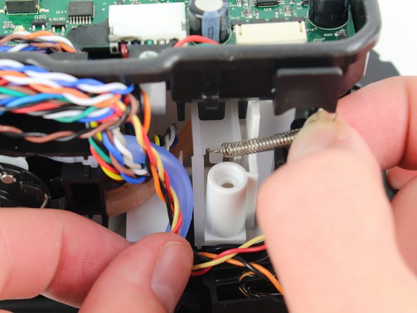
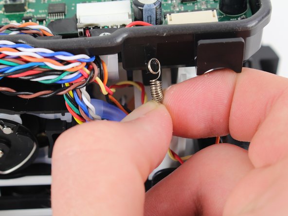
- First pull up, then pull down on the spring to detach it from the hooks.
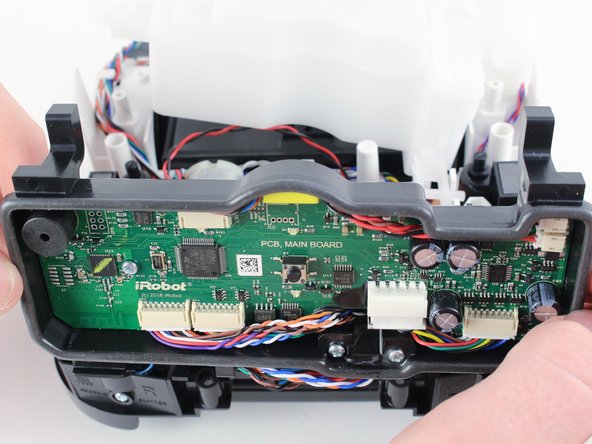
- Lift up on the motherboard case and pull it forward to remove it from the device. This will expose the free-floating platform, as well as motors, water tubing, and the magnetic sensor pads.
- Carefully pry the magnets to raise them up with respect to the free-floating platform, but not so much that they rub against the bottom of the motherboard case.
- The idea is to shrink the gap between the magnet and the motherboard case so as to improve the performance of the inductive sensor.