Acer Spin 7 SP714-51 Keyboard Replacement
ID: 149431
Description: This repair guide will help the user on how to...
Steps:
- Turn the laptop so that the back cover is visible and facing you. Make sure it is on a flat surface such as a table.
- Use a Phillips #0 screwdriver to remove the 6 mm screws along the edge of the bottom cover.
- Once all the screws are removed, you should easily be able to remove the back cover. This can be done by hand or by using a Spudger as seen in the tools list.
- Remove the battery connector cable from the motherboard.
- This will cut power to the laptop, reducing the likelihood of damage and injury.
- Ensure that you are pulling the connector straight back, if you pull up at all you may damage the battery connector on the motherboard.
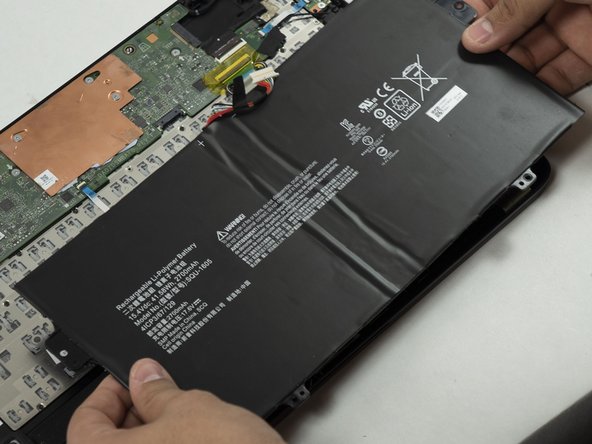
- Use a Phillips #0 screwdriver to remove the last two 3mm long fasteners at the edge of the laptop body, and carefully remove the battery.
- Place the new battery in the battery slot
- Do not bend or puncture the battery.
- Disconnect the white and black antennae from the Wi-Fi card, located on the left side of the laptop. The antennae should snap off upwards easily with a pry tool.
- Unscrew the retaining screw from the Wi-Fi card and unslot the card to remove it from the laptop.
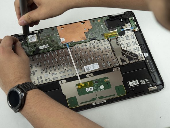
- Lift the tab on the ribbon connector connecting the motherboard to the power switchboard and slide out the connector.
- Remove the 2 screws holding the switchboard in place and remove the switch panel.
- Flip up the tab on the keyboard connector and disconnect the ribbon cable from the motherboard.
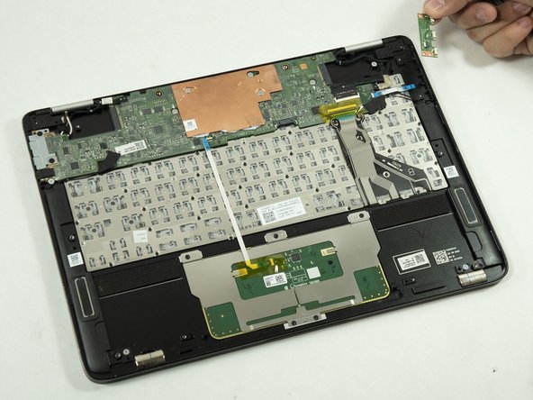
- Remove the display connector by lifting the tape and pulling the connector straight back.
- Remove the trackpad ribbon cable.
- Remove the speaker connectors, lifting the tape and pulling straight back from the connector.
- Remove the touchscreen connector after peeling up the adhesive tape holding it in place.
- Make sure to pull straight back to avoid damaging the connector.
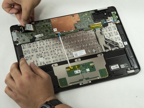
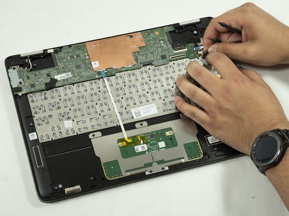
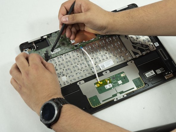
- On the upper left side of the back panel is a protective shield for the USB-C panel. Remove the two 3mm screws holding the panel in place using the PH0 Phillips head screwdriver.
- Gently pull the panel away being careful not to damage anything.
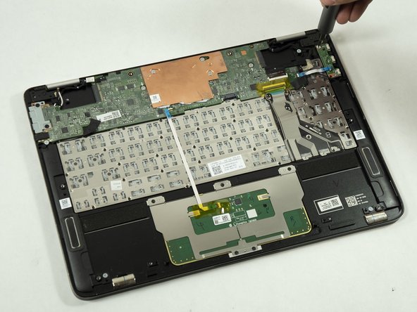
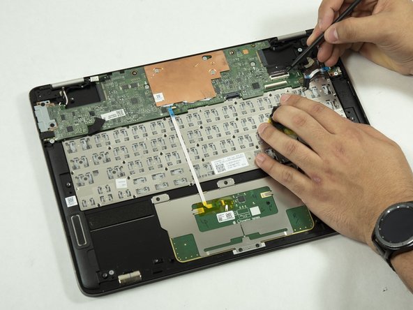
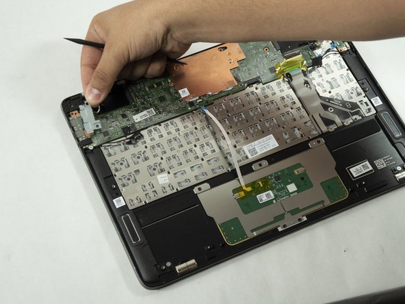
- Unscrew the silver 3mm long screws holding the motherboard using the PH0 bit and remove them carefully to avoid breaking them.
- This will allow the user to get to the keyboard without any other parts in the way making it easier to work with.
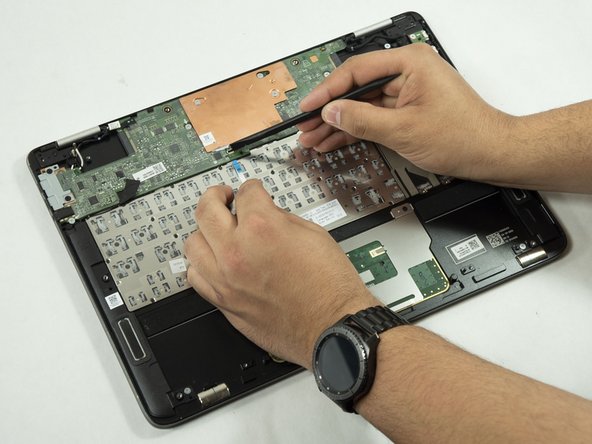
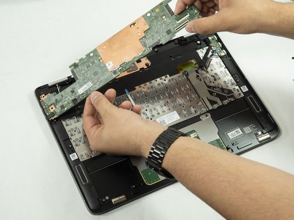
- Partially covering the keyboard is a heatsink, grab the two edges as seen in the photo.
- Carefully pull away the heatsink to gain access to the keyboard.
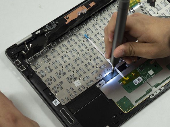
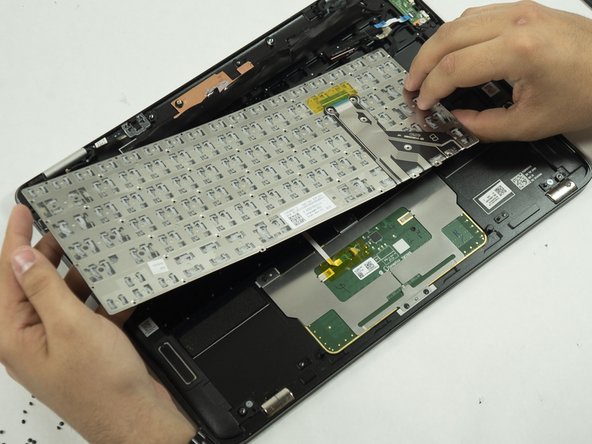
- Use a Phillips #000 screwdriver to remove the 2 mm screws that secure the keyboard in place, and carefully remove the keyboard to avoid breaking it.