Asus Zenbook UX31A Motherboard Replacement
ID: 149524
Description: This guide will show you how to replace the...
Steps:
- Use a T6 screwdriver to remove the ten 6 mm case screws.
- The two screws adjacent to the device serial number stamps are longer than the others. These two screws run about 11 mm long.
- Remove the back cover from the laptop.
- DO NOT BEND OR PUNCTURE THE BATTERY: Puncturing the battery can result in injury since the battery can catch fire or explode when exposed directly to oxygen
- Use a Phillips #00 screwdriver to remove the three 7 mm screws that secure the battery.
- Unplug the bundled battery connector from the motherboard by gently pulling the cable up.
- Make sure you pull the connector directly upwards or you could damage the connector
- Remove the battery from the laptop by lifting it up and out.
- Use a T6 screwdriver to remove the ten 6 mm case screws.
- The two screws adjacent to the device serial number stamps are longer than the others. These two screws run about 11 mm long.
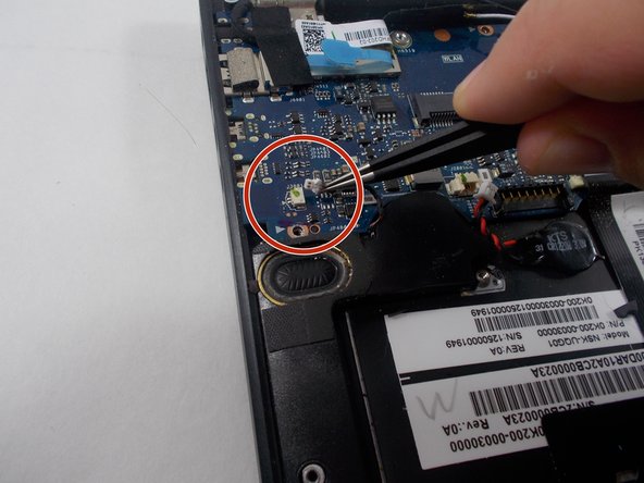
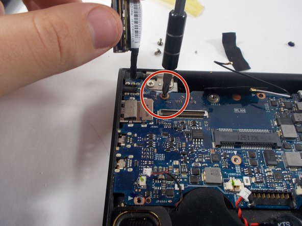
- Use a Phillips #00 screwdriver to remove the two 6 mm screws that secure the Wi-Fi card.
- Wires are loose and easy to disconnect.
- Gently pull the the Wi-Fi card from the motherboard.
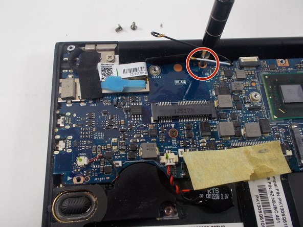
- Disconnect the white and black wire by gently pulling each one up.
- They can be a little tricky to put back on so take your time and be gentle.
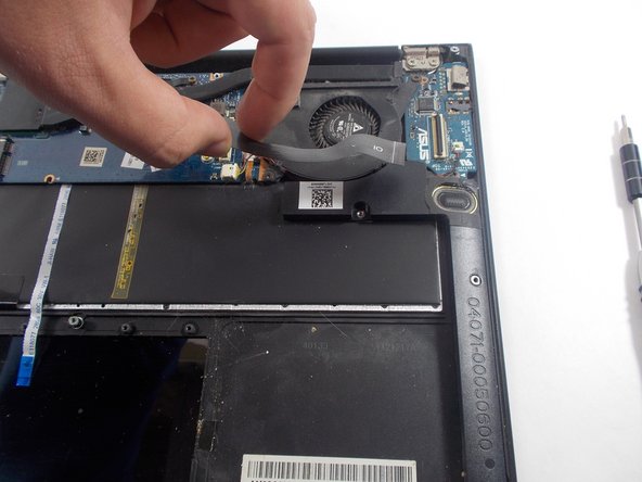
- Unclip both ZIF connector tabs by lifting the black tab up and away from the connector.
- Remove the bridge connector.
- Use a Phillips #00 screwdriver to remove all seven 6 mm screws that secure the fan and heatsink.
- Disconnect the fan connector by pulling on it horizontally until it disconnects.
- Remove the fan.
- Disconnect the bundled connectors by pulling the cable away from the connector in the same direction that the individual wires are running.
- Disconnect the ZIF connector by using the tip of the spudger tool or your fingernail to lift the locking tab. Then, gently pull the cable out.
- To disconnect the display connector, use the iFixit opening tool and pry the connector up and away from the board.
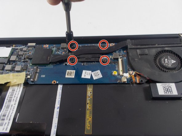
- Use a Phillips #00 screwdriver to remove the four 6 mm screws that hold the motherboard in place.
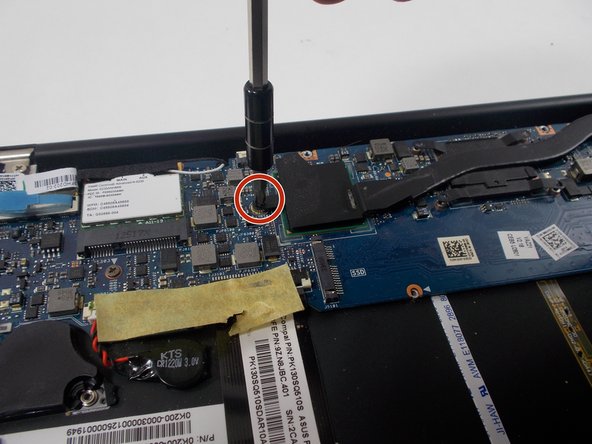
- Use a Phillips #000 screwdriver to remove the single 4 mm screw.
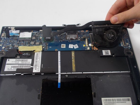
- Remove the motherboard.