Dell Latitude 3510 Keyboard Replacement
ID: 151615
Description: The Dell Latitude 3510 is a rather cheap...
Steps:
- At first you should shut down the system and close the screen.
- Turn over the laptop - here you'll find 8 Phillips head screws that you will have to unscrew.
- Interestingly, the screws won't come off but stay in the D-cover.
- With a pick we look for the gap between the C and D cover and carefully go along the sides.
- Once we have used the pick on all sides, we can carefully remove the housing.
- The case is open but before we do anything stupid remove the battery first
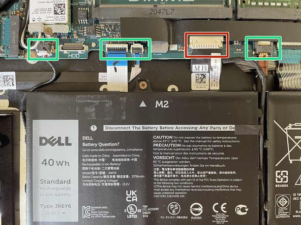
- The battery connector (red border) can be removed with your fingernails or a spudger.
- The ribbon cables (green border) can be removed now. Just flip open the security lock and gently pull the cable out of the socket.
- Before you can remove the battery from the chassis four screws have to be removed.
- The extension board with USB ports, headphone jack, ethernet and sd-card reader is connected to the motherboard via ribbon cables
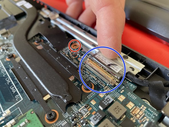
- Remove the screws for the display hinge (red circle) and the ribbon cables (green circle) can be removed after flipping up the securing lock
- The large connector (blue circle) goes to the mainboard and has a metal security clip that needs to be flipped as well to remove
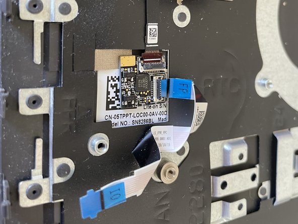
- When all screws and ribbon cable connections have been removed the tiny board can be removed
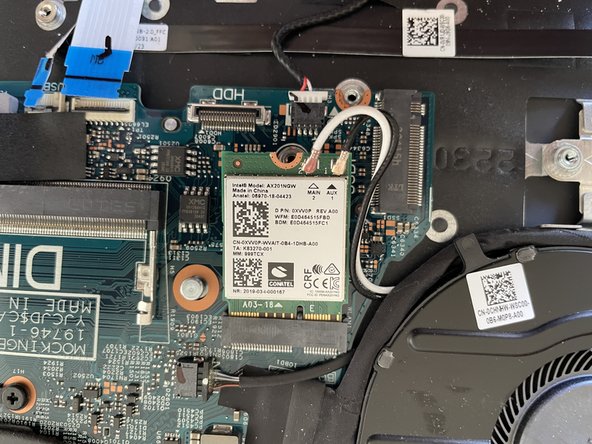
- SSD and Wi-Fi modules are in M2 format and can simply be unscrewed
- Be careful when removing the antenna connectors from the wifi card
- While we are here the last display hinge screws may be unscrewed (red circle) and we can pull the plug on the charging port
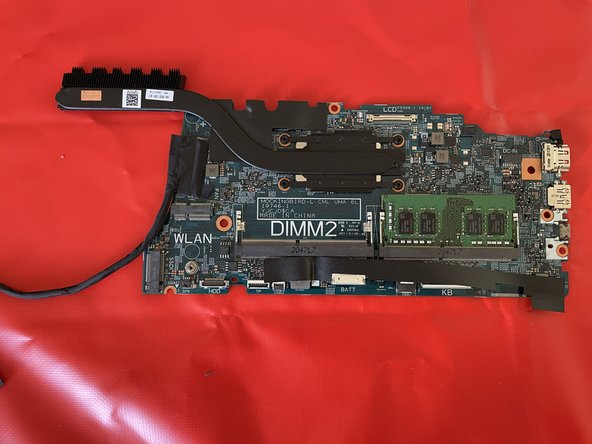
- All visible screws on the mainboard should be removed by this time (the heat sink does not have to be removed).
- The screws on the right side (green circle) still hold the mainboard in place.
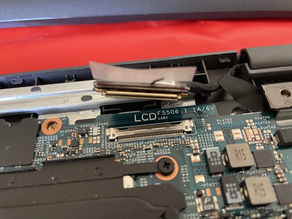
- To remove the connector from the display, look for the metal clip (blue circle) again and carefully pull the connector off it.
- If not done already please remove the last connectors from the mainboard so we can remove it from the c-cover
- Attention: This may be easier with the display assembly removed. To remove it just open the display carefully and it will come off
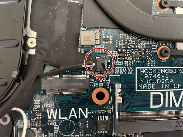
- The fan is only screwed down with 2 screws
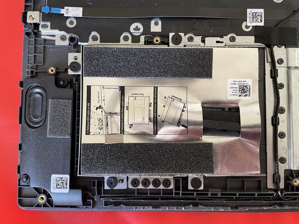
- The hard disk case allows us to add a second hard drive - remove it by unscrewing 4 screws
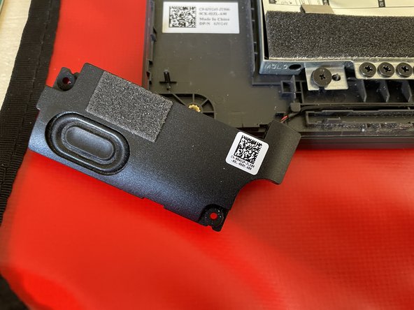
- The two speakers are not screwed in place but clipped down using rubber rings
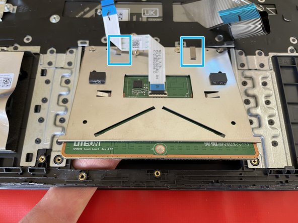
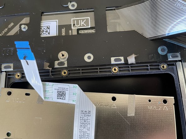
- The touchpad is fixed with 7 screws. Start by loosening the 3 front ones and remove the bracket
- After removing all the screws the touchpad is still held in place by 2 strips of adhesive
- The display should be removed by now. This allows for easy access to the charging port which is secured by a single screw.
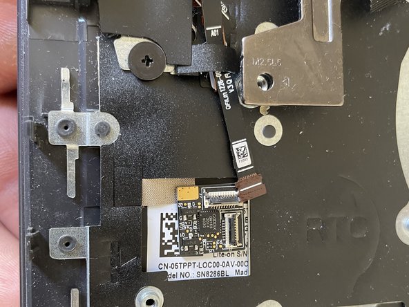
- Additional ribbon cables may be found on the left side of the case.
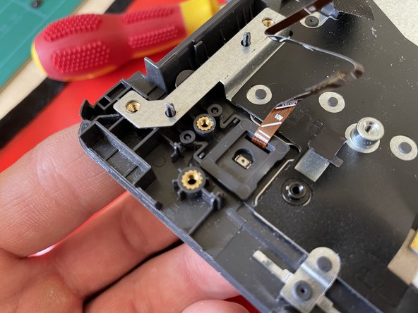
- The ribbon cables we just removed are connected to the power button. To remove it we have to remove two flat-head screws (green circle)
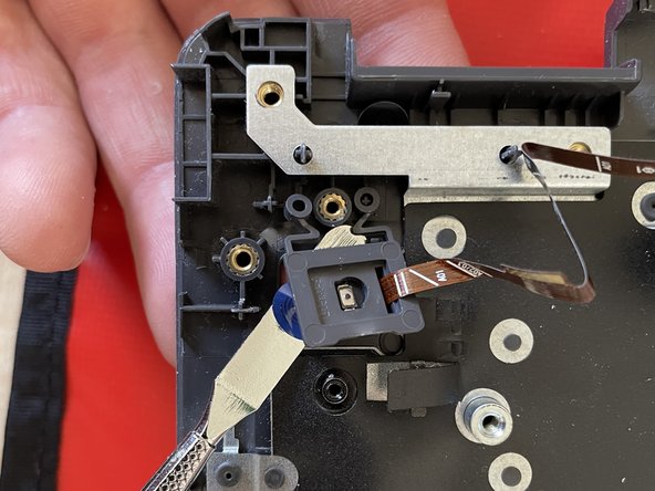
- A small metal bracket hides the power button
- To remove the button from the c-cover gently pry it out with a spudger
- The last parts we need to remove are the small bridging board between power button and extension board (green rectangle) as well as the ssd bracket (pink rectangle). The bridging board is easily removed by using a spudger and the bracket is removable by pushing it down.
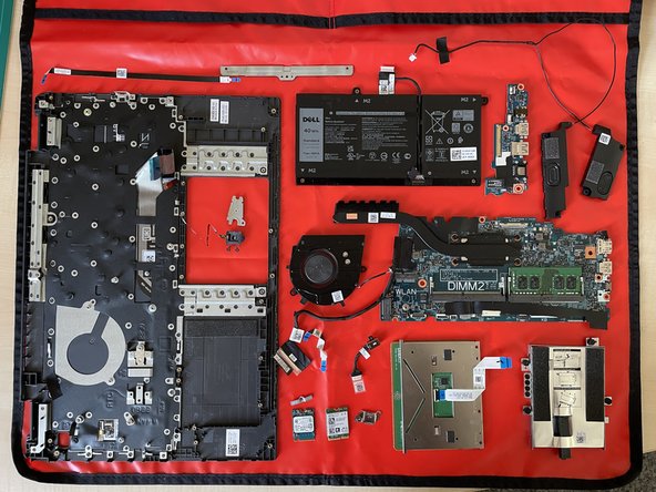
- Now all parts from C-cover and thus the keyboard should be removed and can be placed on the new keyboard.
- Unfortunately the keyboard cannot be separated from the c-cover. To reassemble just follow all steps in reverse order. Happy repairs!