GuliKit KingKong 2 Pro Triggers Replacement
ID: 151694
Description: Use this guide to remove the triggers in your...
Steps:
- Use a Phillips #00 screwdriver to remove the four 11 mm-long screws securing the back cover.
- The back cover of the GuliKit Kingkong 2 Pro is held in place by plastic clips.
- Insert an opening pick into the gap between the front assembly and the back cover at the bottom edge of the controller.
- Tilt your opening pick downwards to widen the gap.
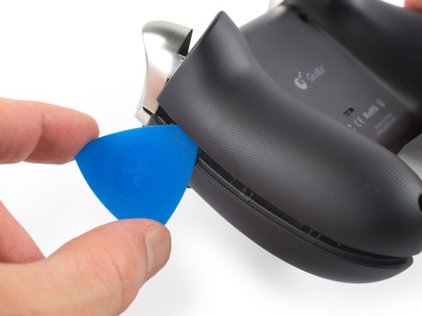
- Insert an opening pick into the gap between the front assembly and the back cover at the outside of the right controller handle.
- Slide the opening pick along the gap to separate the front assembly from the back cover.
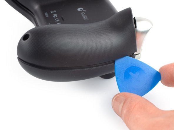
- Insert an opening pick into the gap between the front assembly and the back cover at the outside of the left controller handle.
- Slide the opening pick along the gap to separate the front assembly from the back cover.
- Separate the back cover from the front assembly and remove it.
- It's not mandatory to remove the two vibration motors to remove the mainboard assembly. However, other repairs become much easier with the motors removed. If you want to leave the motors in place, you can jump straight to step 9.
- Pull on the connectors themselves and not the cables to avoid damaging them.
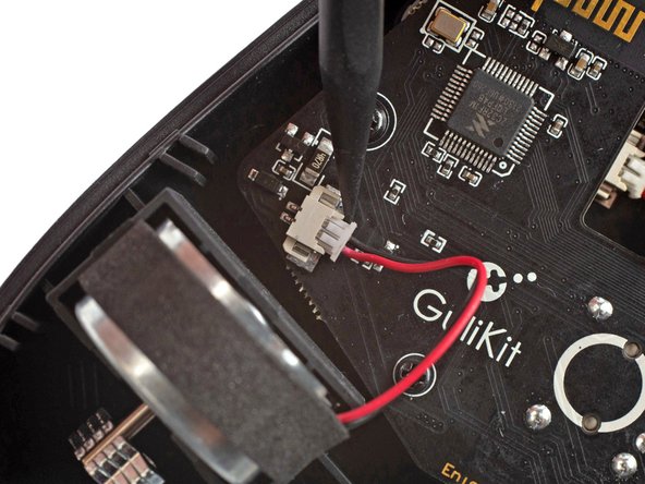
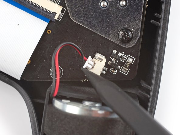
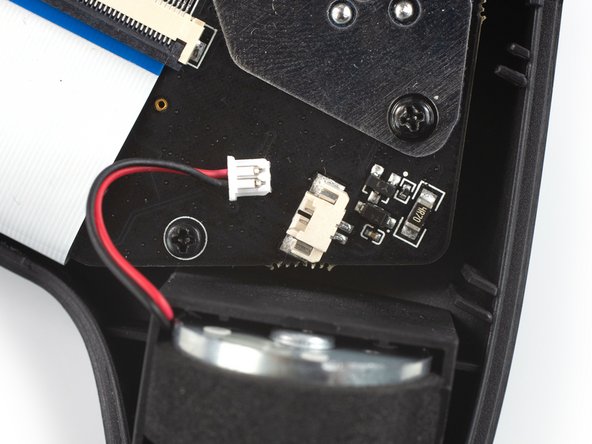
- Use the point of a spudger to disconnect the right vibration motor by pushing the connector straight out of its socket.
- If you can't disconnect the vibration motor with a spudger, use a pair of blunt nose tweezers to pull the connector out of its socket.
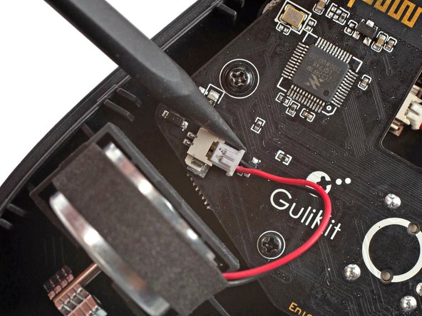
- Use the point of a spudger to disconnect the left vibration motor by pushing the connector straight out of its socket.
- Remove the vibration motors by lifting them out of the controller housing.
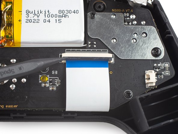
- Use a spudger, an opening tool, or your fingernail to flip up the small, hinged locking flap on the interconnect cable's ZIF connector.
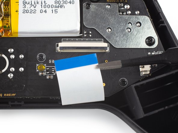
- Use a pair of blunt nose tweezers to disconnect the interconnect cable by pulling the cable straight out of the connector.
- Use a Phillips #00 screwdriver to remove the screws securing the mainboard assembly:
- Four 7.8 mm-long screws.
- Two 11 mm-long screws.
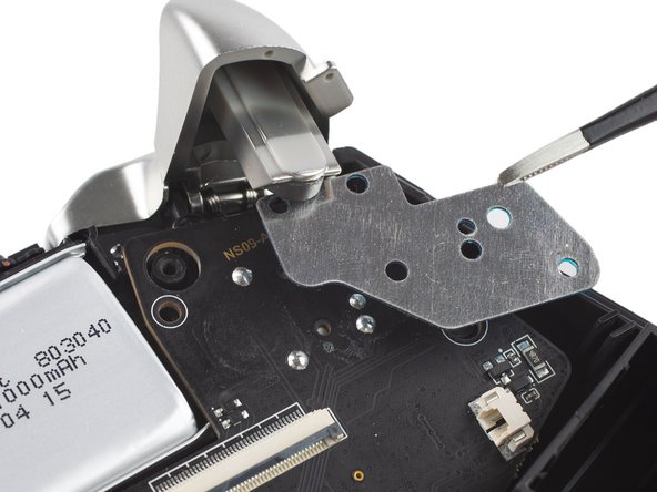
- Use a pair of blunt nose tweezers to remove the metal shield from the mainboard assembly.
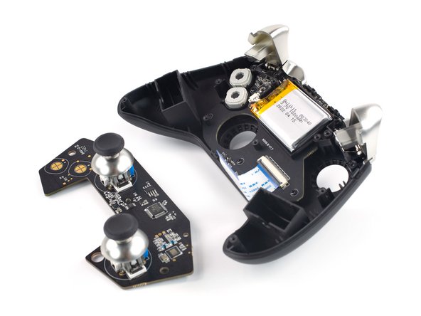
- Remove the mainboard assembly by lifting it out of the controller housing.
- Take care not to puncture the battery with your tool—a punctured battery may leak dangerous chemicals or cause a fire.
- Use a Phillips #00 screwdriver to remove the single 7.8 mm-long screw securing the battery frame.
- Free the battery frame by lifting it off the plastic pins holding it in place.
- Pull on the connectors themselves and not the cables to avoid damaging them.
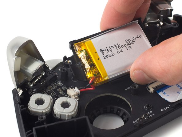
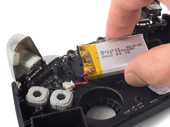
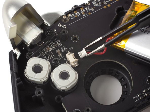
- Use a pair of blunt nose tweezers to disconnect the battery connector by pulling it straight out of its socket.
- Remove the battery and its frame from the controller housing.
- Use a Phillips #00 screwdriver to remove the four 7.8 mm-long screws securing the triggers.
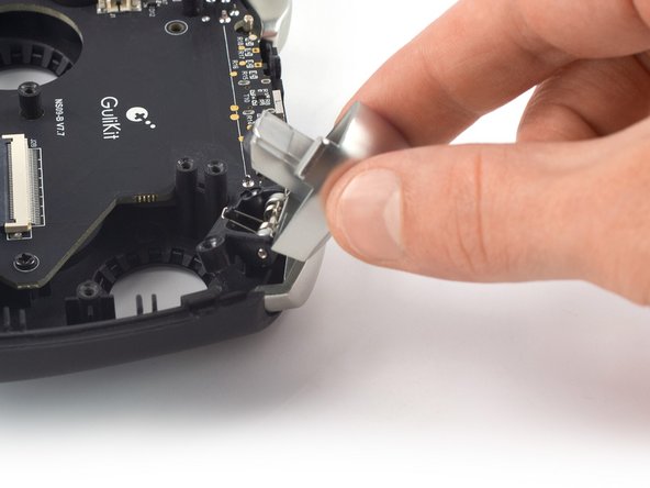
- Use your fingers to lift the left trigger off its bracket.
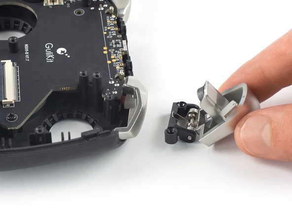
- Remove the left trigger.
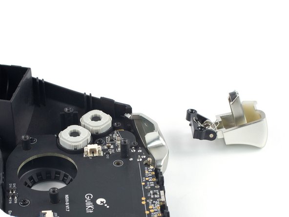
- Repeat the previous procedure and lift the right trigger off its bracket to remove it.