iPad Pro 11" 3rd Gen Battery Replacement
ID: 151810
Description: Follow this guide to replace the battery in...
Steps:
- Allow your iPad's battery to fully drain before starting this repair. A charged battery may catch fire if damaged during the repair.
- Unplug any cables and fully shut down your iPad.
- If your battery is swollen, take appropriate precautions.
- While your iPad looks uniform from the outside, there are delicate components under portions of the screen. To avoid damage, follow instructions exactly as written and note the following areas as you open your iPad:
- Camera module, ambient light sensors, proximity senor, and front microphone
- Display cables
- Screen magnets
- LCD edges
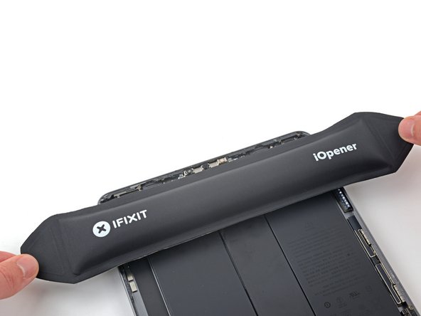
- Apply a heated iOpener to the right edge of the screen for two minutes.
- You can also use a hair dryer, heat gun, or hot plate—but extreme heat can damage the screen and/or internal battery, so proceed with care.
- The next three steps demonstrate the Anti-Clamp, a tool we designed to make the opening procedure easier. If you aren't using the Anti-Clamp, skip down three steps for an alternate method.
- For complete instructions on how to use the Anti-Clamp, check out this guide.
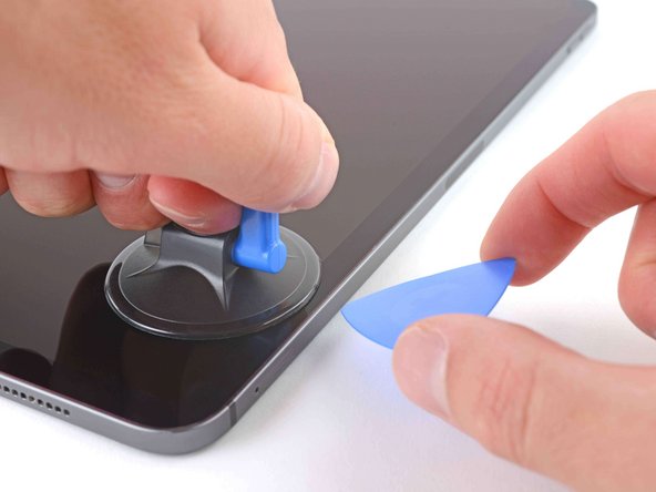
- Pull the blue handle backward to unlock the Anti-Clamp's arms.
- Place an object under your iPad so it rests level between the suction cups.
- Position the suction cups near the middle of the right edge—one on the top, and one on the bottom.
- Hold the bottom of the Anti-Clamp steady and firmly press down on the top cup to apply suction.
- If you find that the surface of your iPad is too slippery for the Anti-Clamp to hold onto, use tape to create a grippier surface.
- Pull the blue handle forward to lock the arms.
- Turn the handle clockwise 360 degrees or until the cups start to stretch.
- Make sure the suction cups remain aligned with each other. If they begin to slip out of alignment, loosen the suction cups slightly and realign the arms.
- Wait one minute to give the adhesive a chance to release and present an opening gap.
- If your screen isn't getting hot enough, you can use a hair dryer to heat along the right edge of the iPad.
- For complete instructions on how to use a hair dryer, check out this guide.
- Insert an opening pick under the screen when the Anti-Clamp creates a large enough gap.
- If the Anti-Clamp doesn't create a sufficient gap, apply more heat to the area and rotate the handle clockwise half a turn.
- Don't crank more than a half a turn at a time, and wait one minute between turns. Let the Anti-Clamp and time do the work for you.
- Skip the next step.
- If your screen is badly cracked, covering it with a layer of clear packing tape may allow the suction cup to adhere. Alternatively, very strong tape may be used instead of the suction cup. If all else fails, you can superglue the suction cup to the broken screen.
- Apply a suction handle to the right edge of the screen, about 5 cm from the bottom edge.
- Pull up on the suction handle with firm, constant pressure to create a gap just small enough to insert an opening pick.
- Only create a gap small enough to insert an opening pick. Overbending the screen will damage it.
- Insert the tip of an opening pick into the gap.
- Don't insert the opening pick more than 5 mm or you may damage the LCD.
- Insert a new opening pick in the gap you just created.
- Slide the pick along the right edge to separate the adhesive.
- When sliding near the volume buttons, don't insert the pick more than 2 mm or you'll damage the screen magnets.
- Leave the pick in the top right corner to prevent the adhesive from re-sealing.
- Apply a heated iOpener to the top edge of the screen for two minutes.
- The top edge of the iPad contains the camera module, two ambient light sensors, the proximity sensor, and front microphone. These components are fragile and easily damaged if an opening pick is inserted too far. Only separate the adhesive in the marked locations to avoid damage.
- The two ambient light sensors can be hard to see and can be located using a flashlight or by placing the iPad under a bright light.
- Don't insert an opening pick more than 2 mm near the top left and right edges or you'll damage the ambient light sensors.
- Don't insert an opening pick more than 1 mm near the middle of the top edge or you'll damage the camera module, proximity sensor, and front microphone.
- Insert a new opening pick in the gap you just created.
- Slide the pick along the top right edge, stopping when you reach the right ambient light sensor.
- Don't insert the opening pick more than 5 mm.
- Leave the pick in to prevent the adhesive from re-sealing.
- Insert a new opening pick to the right of the ambient light sensor.
- Slide the pick along the middle section of the top edge, stopping when you reach the left ambient light sensor.
- Don't insert the pick more than 1 mm or you'll damage the proximity sensor and front microphone.
- Leave the pick in to prevent the adhesive from re-sealing.
- Insert a new opening pick to the left of the ambient light sensor.
- Slide the pick along the top left edge, stopping when you reach the left ambient light sensor.
- Don't insert the opening pick more than 5 mm.
- Once the top edge adhesive has been separated, you can remove the two picks near the ambient light sensors.
- Apply a heated iOpener to the bottom edge of the screen for two minutes.
- Insert a new opening pick in the bottom right corner below the existing pick.
- Don't insert the opening pick more than 2 mm when sliding on the right edge.
- Slide the pick around the bottom right corner to separate the adhesive.
- Slide the opening pick along the bottom edge, stopping at the USB-C port.
- Don't insert the opening pick more than 5 mm when separating the bottom edge adhesive.
- Leave the pick in to prevent the bottom edge adhesive from re-sealing.
- Insert a new opening pick to the left of the USB-C port.
- Separate the remaining bottom edge adhesive.
- Don't insert the opening pick more than 5 mm when slicing the bottom edge adhesive.
- Leave the pick in the bottom left corner to prevent the bottom edge adhesive from re-sealing.
- Apply a heated iOpener to the left edge of the screen for two minutes.
- The left edge of the iPad contains several display cables. These cables are extremely fragile and easily damaged if an opening pick is inserted too far or at the wrong angle. Follow the instructions exactly as written to avoid damage.
- The display cables are located within small indents of the frame and require an opening pick to be inserted at a 45° angle.
- There are flat sections of the frame which require an opening pick to be inserted horizontally.
- Insert an opening pick at a 45˚ angle just above the bottom left corner.
- Don't insert the pick more than 5 mm or you'll damage the display cables.
- Carefully slide the pick along the left edge, stopping when you reach the flat section of the frame.
- Lower the opening pick so it is horizontal to the screen.
- Don't insert the pick more than 5 mm.
- Continue separating the left edge adhesive until you reach the next indented section of the frame.
- Separate the remaining adhesive, making sure to follow the instructions exactly as written.
- Slide the pick at a 45˚ downward angle and don't insert the pick more than 5 mm.
- Slide the pick horizontally and don't insert the pick more than 5 mm.
- At this point, you've separated most of the screen adhesive. Lift the edges of the screen up slightly to check if there is any remaining adhesive.
- Use an opening pick to remove any remaining adhesive keeping the screen stuck to the frame.
- Grab the top right and bottom left corners of the screen.
- Slowly slide the screen towards the bottom right corner to separate it from the frame.
- Don't fully remove the screen as it is held in place by several ribbon cables underneath.
- Shift the screen towards the bottom right corner of the frame until the ambient light sensor ribbon cable near the top edge is uncovered.
- Throughout this repair, keep track of each screw and make sure it goes back exactly where it came from.
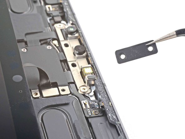
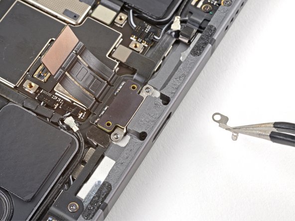
- Use a Phillips screwdriver to remove the two screws securing the ambient light sensor cable bracket to the logic board:
- One 1.3 mm screw
- One 2.0 mm screw
- During reassembly, this is a good point to power on your iPad and test all functions before sealing it up. Be sure to power your iPad back down before you continue working.
- Use a pair of tweezers or your fingers to remove the bracket.
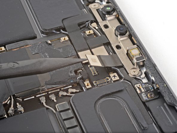
- Use the flat end of a spudger to disconnect the ambient light sensor cable by lifting straight up on the press connectors.
- To re-attach press connectors like this one, carefully align and press down on one side until it clicks into place, then repeat on the other side. Do not press down on the middle. If the connector is misaligned, the pins can bend and cause permanent damage.
- Don't try to remove the screen yet, as it's still attached by delicate ribbon cables.
- Grip the right edge of the screen and fold it open like a book.
- Lay the screen down over the left edge of the iPad.
- Use a Phillips screwdriver to remove the five screws securing the lower cable shield to the logic board:
- Two 2.0 mm screws
- Three 1.3 mm screws
- Use tweezers or your fingers to grab and remove the lower cable shield.
- Use a Phillips screwdriver to remove the 1.8 mm screw securing the battery connector to the logic board.
- Use the pointed end of a spudger to pry up and disconnect the top two display cables.
- Disconnect the two remaining display cables.
- Grip the right edge of the screen and lift it away.
- During reassembly, before installing a screen, remove any remaining adhesive from the frame, and clean the glued areas with high-strength (>90%) isopropyl alcohol and a lint-free cloth. This helps prep the iPad for fresh adhesive and ensures that it will bond properly.
- If you plan to reinstall your existing screen, remove any remaining adhesive from the back and clean the adhered areas with isopropyl alcohol.
- Follow this guide to install pre-cut adhesive strips on your iPad's screen before sealing it up.
- Use the flat end of a spudger to disconnect the USB-C port cable.
- The USB-C port cable is secured to the logic board with weak adhesive.
- Slide an opening pick between the cable and the logic board to separate the adhesive.
- Use a Phillips screwdriver to remove the two 1.9 mm screws securing the USB-C port to the frame.
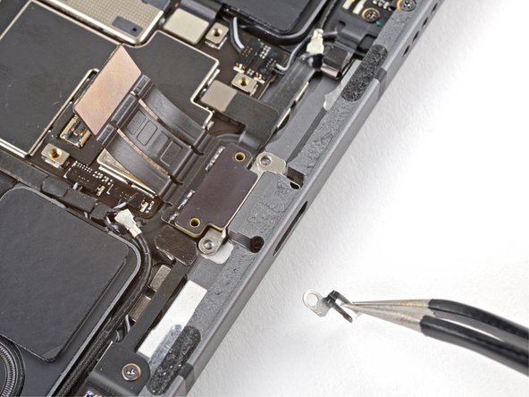
- Use tweezers to remove the two grounding contacts from each side of the USB-C port.
- Lift up and remove the USB-C port.
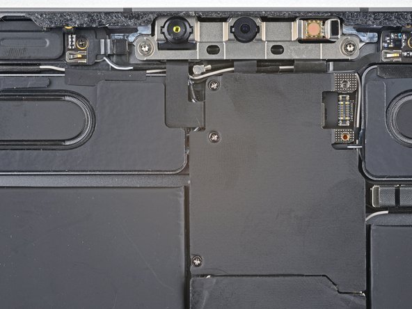
- Use a Phillips screwdriver to remove the three 1.2 mm screws securing the top cable shield.
- Apply a heated iOpener to the top cable shield for one minute to soften the adhesive securing it to the logic board.
- Insert an opening pick under the top cable shield and gently pry up to separate the adhesive.
- Use tweezers or your fingers to grab and remove the top cable shield.
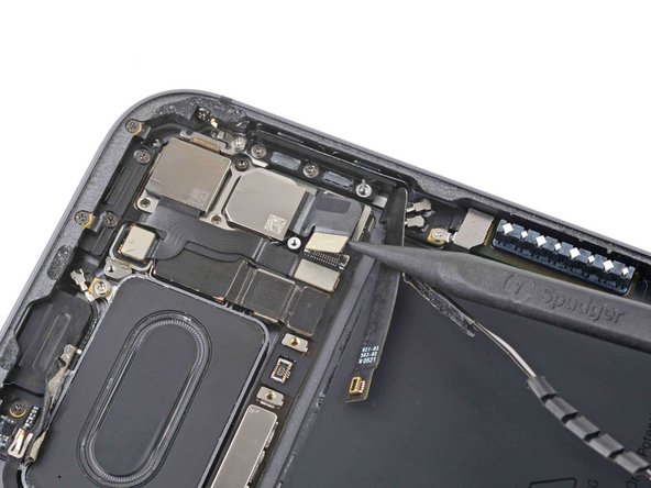
- Use the pointed end of a spudger to disconnect the IR dot projector cable.
- Use the pointed end of a spudger to disconnect the front-facing camera and Face ID camera.
- Use a Torx T3 screwdriver to remove the two 2.1 mm screws securing the front camera assembly to the frame.
- Use the pointed end of a spudger to pry up and loosen the front camera assembly.
- Use tweezers or your fingers to remove the front camera assembly.
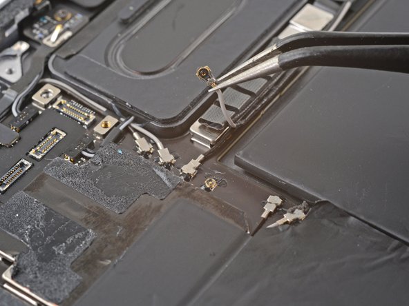
- To disconnect antenna cables like this, use tweezers to grip the connector near the cable and lift it up.
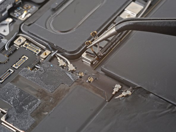
- Use tweezers to disconnect the two antenna cables.
- Be careful using tweezers or other pointy metal tools near the battery—a punctured battery may leak dangerous chemicals or cause a fire.
- To reinstall, hold the connector in place and gently press straight down. The connector will “snap” into its socket much like the metal snaps on a jacket.
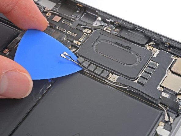
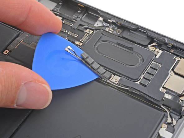
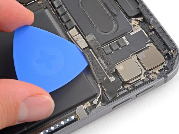
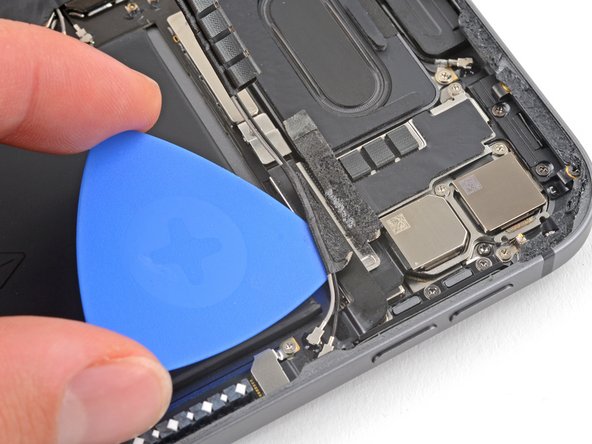
- The antenna cables are secured to the logic board with weak adhesive.
- Slide an opening pick under the antenna cables to separate them from the logic board.
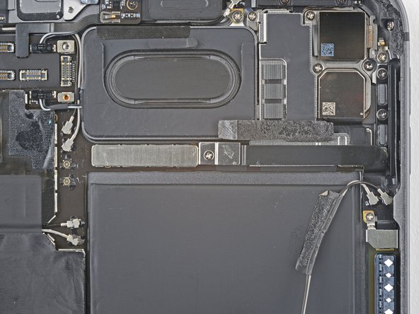
- Use an opening pick to separate the thin foam covering the antenna cables.
- The antenna cables are secured to the mmWave interconnect cable with weak adhesive.
- Slide an opening pick between the antenna cables and the mmWave interconnect cable to separate them.
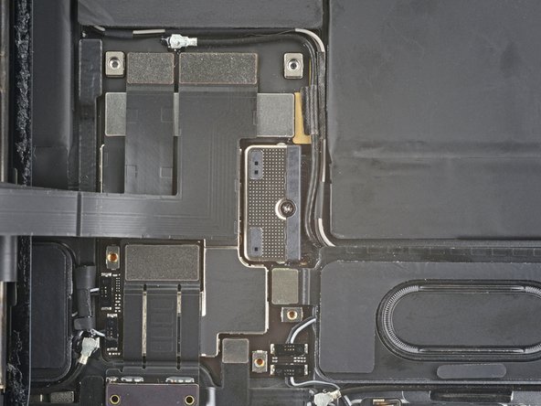
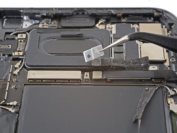
- Use a Phillips screwdriver to remove the 1.2 mm screw securing the press connector bracket to the logic board.
- Use tweezers or your fingers to remove the antenna cable bracket.
- Be careful using tweezers or other pointy metal tools near the battery—a punctured battery may leak dangerous chemicals or cause a fire.
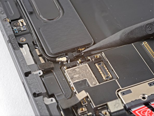
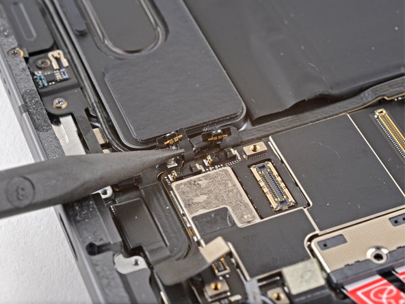
- Use the flat end of a spudger to disconnect the mmWave flex cable.
- Slide an opening pick under the mmWave flex cable to separate it from the logic board.
- Some of these screws are the same length but have different thread sizes. Don't mix up the screws or you'll damage the threads in the frame.
- Use your Phillips screwdriver to remove the six screws securing the rear camera shield to the frame:
- Two 2.8 mm screws
- One 1.9 mm screw
- One 1.9 mm screw
- One 1.2 mm screw
- One 1.2 mm screw
- Use tweezers or your fingers to lift the right side of the camera shield up.
- Slide the shield out horizontally.
- During reassembly, lower the left side of the shield back into place and make sure the small protruding tab is slotted in, then hinge the shield closed.
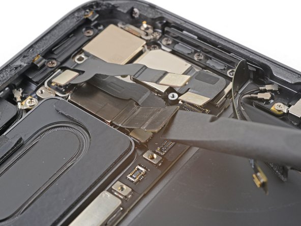
- Use the pointed end of a spudger to disconnect the wide angle camera cable.
- Use the pointed end of a spudger to disconnect the power button and LED cable.
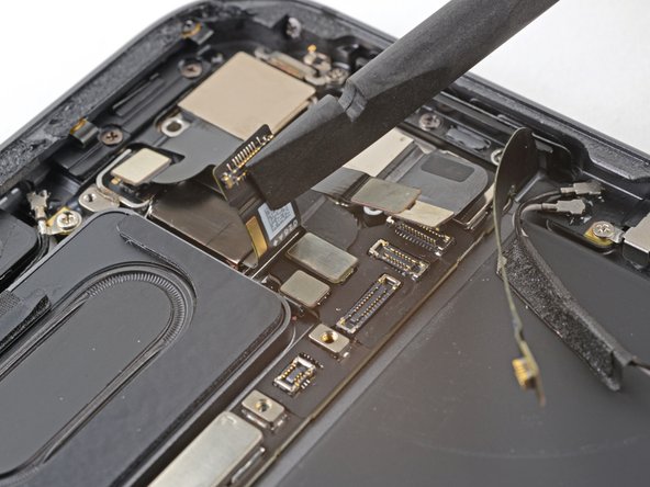
- Use the flat end of a spudger to disconnect the LiDAR sensor cable.
- Fold the LiDAR sensor cable away from the frame to access the press connectors underneath.
- Only fold the cable enough to access the connector underneath.
- Use the pointed edge of a spudger to disconnect the ultra wide camera cable.
- Use the flat end of a spudger to gently pry up and loosen the rear camera module.
- Use tweezers or your fingers to grab and remove the rear camera module.
- You're about to disconnect many connectors from the top and bottom of the logic board. During reassembly, use these photos as a reference to ensure all cables are connected in the correct locations.
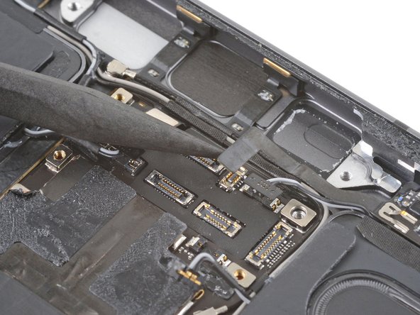
- Use the pointed end of a spudger to disconnect the two top right speaker press connectors.
- Don't pry against the short sides of the connector. The socket on the logic board is delicate and may break off if pried against.
- Repeat the previous step for the two top left speaker cables.
- Use the pointed edge of a spudger to disconnect the top microphone cable.
- Use the pointed end of a spudger to disconnect the top right sensor cable.
- Use the pointed edge of a spudger to disconnect the top interconnect board.
- Don't bend or reposition the interconnect board. It's stiff and will break if overbent.
- Use tweezers to disconnect the two top left antenna cables.
- The antenna cables located next to the top right speaker.
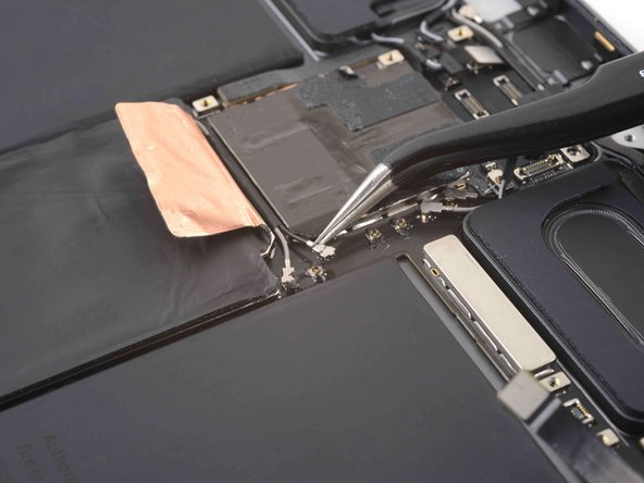
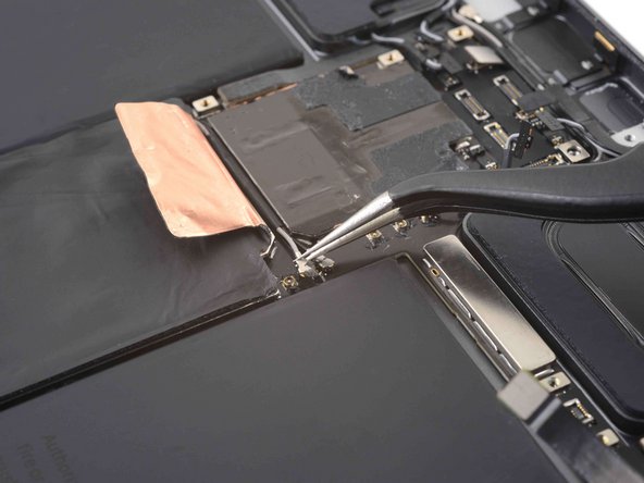
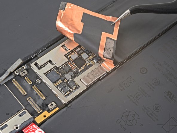
- Use tweezers to peel back the logic board shielding tape covering the two antenna cables.
- Be careful using tweezers or other pointy metal tools near the battery—a punctured battery may leak dangerous chemicals or cause a fire.
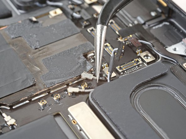
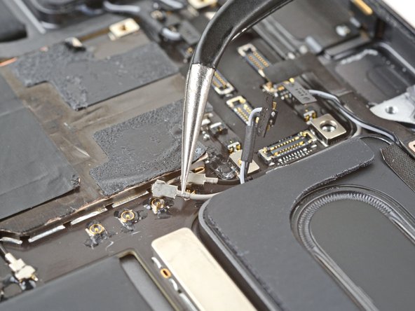
- Use tweezers to disconnect the two bottom right antenna cables.
- Be careful using tweezers or other pointy metal tools near the battery—a punctured battery may leak dangerous chemicals or cause a fire.
- Use the pointed edge of a spudger to disconnect the bottom interconnect board.
- Don't bend or reposition the interconnect board. It's stiff and will break if overbent.
- Use tweezers to disconnect the Wi-Fi antenna coaxial cable.
- Use the pointed end of a spudger to disconnect the Smart Connector cable.
- Follow the procedure in step 65 to disconnect the bottom right speaker.
- Follow the procedure in step 65 to disconnect the bottom right speaker.
- Gently pull the antenna cables away from the logic board.
- Continue repositioning the antenna cables until they are clear from the bottom of the logic board.
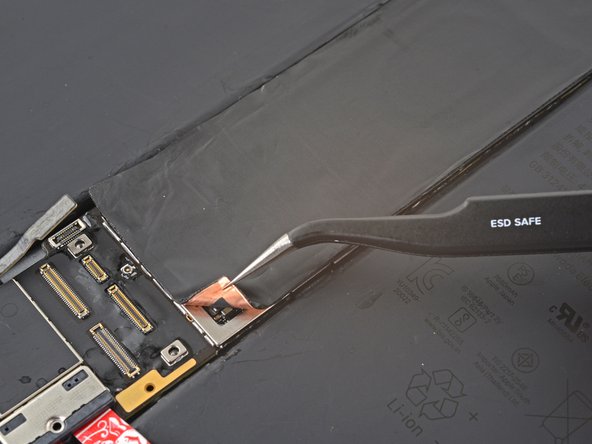
- Use tweezers or your fingers to peel back the logic board shielding to reveal the hidden press connectors.
- Be careful using tweezers or other pointy metal tools near the battery—a punctured battery may leak dangerous chemicals or cause a fire.
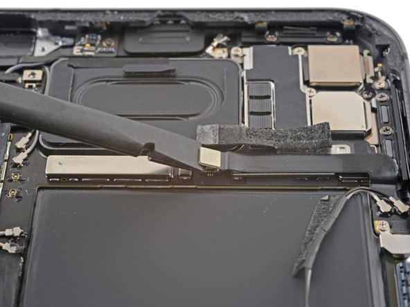
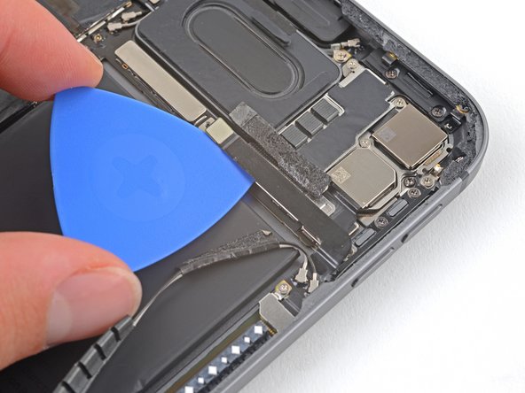
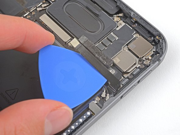
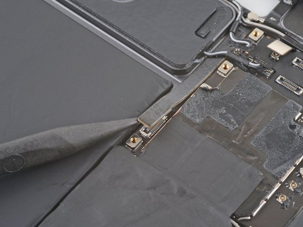
- Use the flat end of a spudger to slide out the cable bracket.
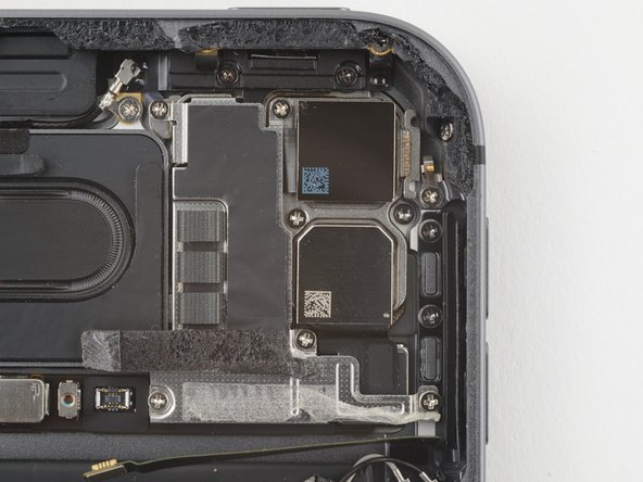
- Use tweezers or your fingers to remove the bracket.
- Use the flat end of a spudger to disconnect the left microphone and Apple Pencil charger cables.
- The adhesive that secures the logic board to the frame is very strong. To remove the board, follow the next steps to weaken the adhesive using high-strength (>90%) isopropyl alcohol.
- Elevate the left side of the iPad so that it lays down at an angle.
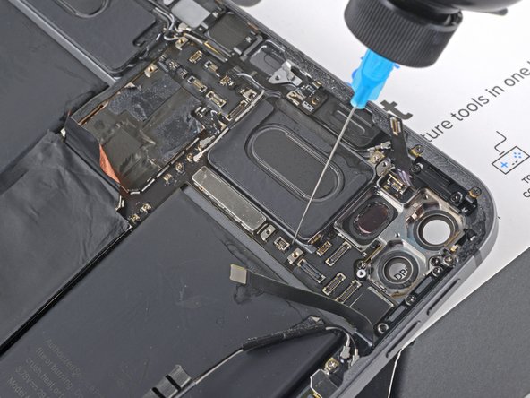
- Apply a few drops of isopropyl alcohol along the left edge of the logic board.
- Be careful if you're using a syringe with a needle or other sharp instrument to dispense isopropyl alcohol—a punctured or bent battery may leak dangerous chemicals or cause a fire.
- Let the alcohol soak for one minute to soften the adhesive under the logic board.
- Rotate your iPad 180˚ and lay it down with the right side elevated.
- Repeat the previous step for the right edge of the logic board.
- Elevate the top side of the iPad.
- Apply a few drops of isopropyl alcohol to the right branch of the logic board near the rear camera glass.
- Don't allow isopropyl alcohol to contact the rear camera glass or you'll damage them.
- Let the alcohol soak for one minute to soften the adhesive under the right logic board branch.
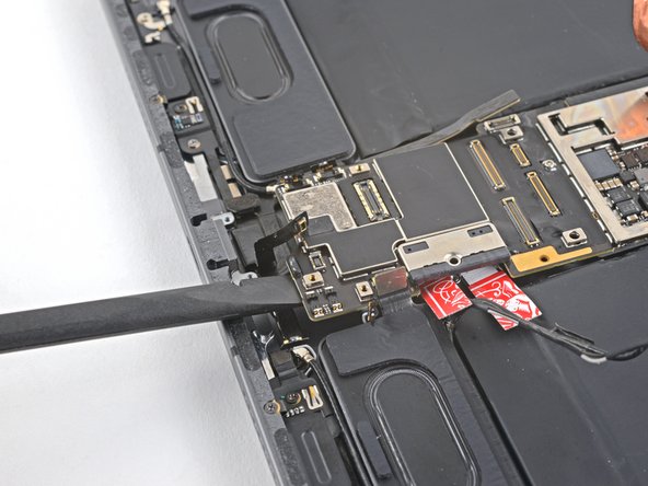
- Insert the flat end of a spudger under the lower edge of the logic board.
- Don't pry against the bottom interconnect board as this will damage it.
- Slowly lift up the bottom of the logic board.
- If the adhesive is still too strong to lift up the logic board, apply some additional isopropyl alcohol and wait one minute.
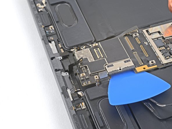
- Lift up the logic board and replace the playing card battery blocker with an opening pick.
- Slide an opening pick under the left edge of the logic board to loosen it.
- Pry against the frame underneath the logic board to separate the adhesive.
- Don't forcefully lever against the battery—a punctured or bent battery may leak dangerous chemicals or cause a fire.
- If the adhesive is still too strong to lift up the logic board, apply some additional isopropyl alcohol and wait one minute.
- Use an opening pick to gently pry up the top right branch of the logic board near the rear camera lenses.
- If the adhesive is still too strong to lift up the logic board, apply some additional isopropyl alcohol and wait one minute.
- Insert an opening pick under the right edge of the logic board above the left microphone and Apple Pencil charger cables.
- Slide the opening pick under the right edge of the logic board to loosen it.
- Pry against the frame underneath the logic board to separate the adhesive.
- Don't forcefully lever against the battery—a punctured or bent battery may leak dangerous chemicals or cause a fire.
- If the adhesive is still too strong to lift up the logic board, apply some additional isopropyl alcohol and wait one minute.
- Use the flat end of a spudger to lift the top edge of the logic board.
- Grip the top and bottom edges of the logic board.
- Remove the logic board.
- There are 11 stretch-release adhesives that secure the battery to the frame. Each adhesive strip has a black pull tab:
- Six on the inside edge of the left battery
- Five on the inside edge of the right battery
- The remainder of the adhesive is located along the bottom edge of the battery.
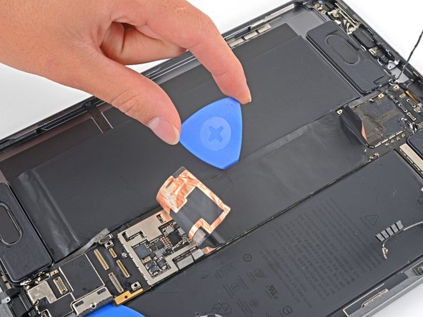
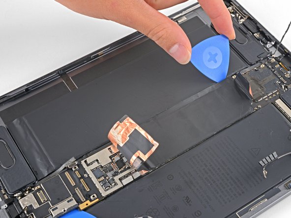
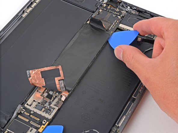
- Use your fingernail or tweezers to peel each pull tab from the edge of the battery without removing them.
- Be careful not to deform or puncture the battery—especially if you're using tweezers.
- Pull the strip out slowly and steadily at a low angle. Give it plenty of time to stretch and un-stick from under the battery.
- You can use a spudger to help keep the strip flat while pulling.
- If the adhesive strip breaks off, try to retrieve it using your fingers or blunt tweezers, and continue pulling—but don't pry under the battery.
- If you removed all of the stretch-release adhesive, good job! You can skip the next four steps. If not, then follow the next four steps to apply isopropyl alcohol.
- Prop the left side of the iPad up against an object so the isopropyl alcohol can flow under the right battery cell.
- Apply high-strength (>90%) isopropyl alcohol along the inside edge of the right battery cell.
- Be careful if you're using a syringe with a needle or other sharp instrument to dispense isopropyl alcohol—a punctured or bent battery may leak dangerous chemicals or cause a fire.
- Let the alcohol soak for two minutes to soften the adhesive under the battery cell.
- Rotate the iPad 180 degrees so the inner edge of the left battery is facing up.
- Repeat the previous step on the left battery cell.
- Lay the iPad down flat on your work surface.
- Starting at the top, insert a plastic card under the right battery cell.
- Slide the plastic card toward the bottom of the iPad to separate the adhesive.
- Stop sliding when you reach the Apple Pencil charger cable.
- Don't force the card or bend the battery. If it's difficult to insert or slide the card, apply more isopropyl alcohol.
- Repeat the previous step for the left battery.
- Stop sliding when you reach the left microphone cable.
- Don't try to remove the battery yet – the battery boards are still held in place with adhesive.
- Lift up the left battery cell.
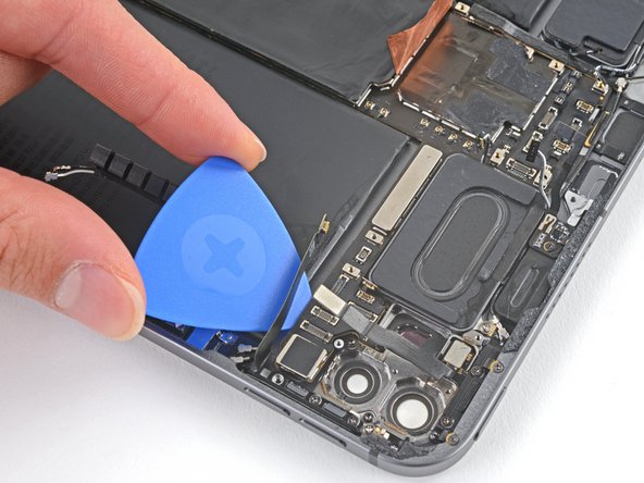
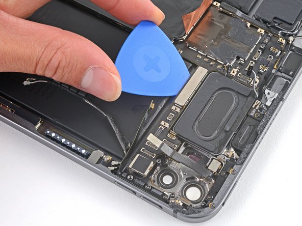
- Insert an opening pick under the left battery board and separate the remaining adhesive securing it to the frame.
- If the adhesive does not separate easily, apply some high-strength (>90%) isopropyl alcohol and wait one minute.
- Repeat the previous step for the right battery cell.
- Lift both halves of the battery out of the iPad at the same time.
- Do not reuse the battery after it has been removed, as doing so is a potential safety hazard. Replace it with a new battery.
- Remove the old battery adhesive from the frame using tweezers and high-strength (>90%) isopropyl alcohol with a lint-free cloth where needed.
- If your battery doesn't come with preinstalled adhesive, use Tesa tape to reattach the battery to the rear case.