Motherboard
ID: 151850
Description: This is a prerequisite-only guide! This guide...
Steps:
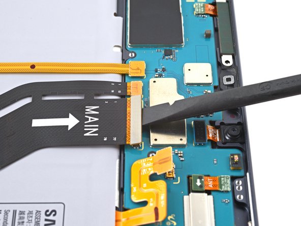
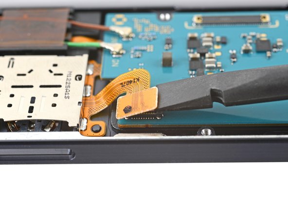
- Use the flat end of a spudger to pry up and disconnect the display cable's press connector secured to the motherboard.
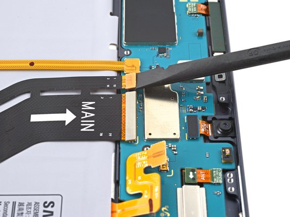
- Repeat for the fingerprint sensor cable attached to display cable.
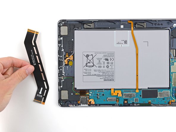
- Use your fingers to remove the display cable.
- Set the cable aside. You'll reuse it during reassembly.
- Use the flat end of a spudger to pry up and disconnect the keyboard dock port cable's press connector secured to the motherboard.
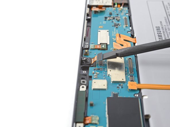
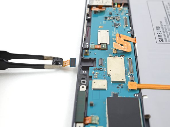
- Use the flat end of a spudger to pry up and disconnect the front camera's press connector secured to the motherboard.
- Use tweezers, or your fingers, to remove the front camera.
- Use the flat end of a spudger to pry up and disconnect the microSD card reader's press connector secured to the motherboard.
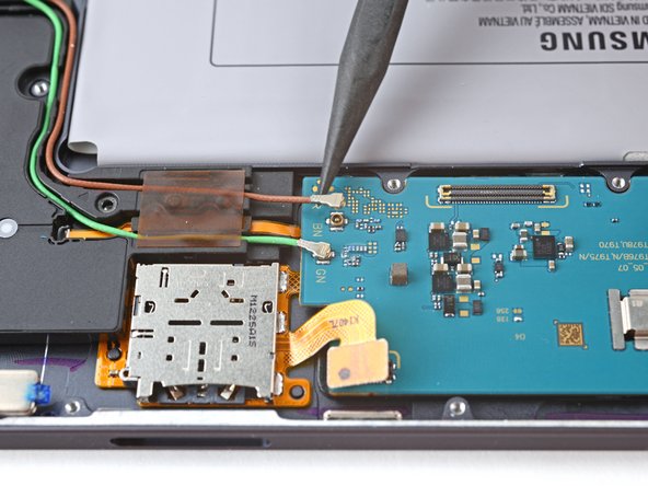
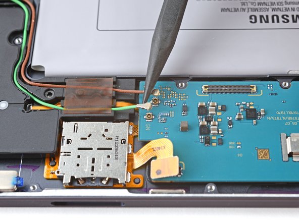
- Use the point of a spudger to carefully pry up and disconnect the green coaxial cable from the left side of the motherboard.
- Repeat this process for the brown coaxial cable.
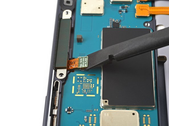
- Use the flat end of a spudger to pry up and disconnect the 5G mmWave antenna's press connector secured to the motherboard.
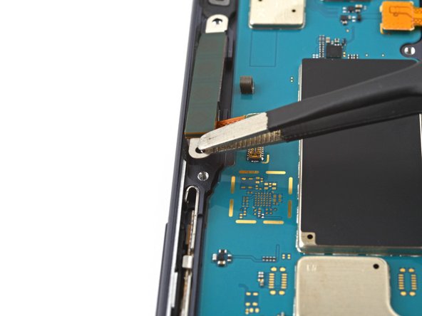
- Use tweezers to pull the antenna out of the frame by its bracket.
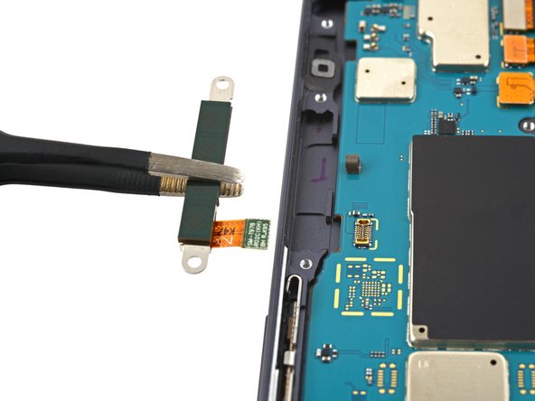
- Remove the 5G mmWave antenna.
- Set the antenna aside. You'll reuse it during reassembly.
- Use the flat end of a spudger to pry up and disconnect the rear camera's two press connectors secured to the motherboard.
- Use the flat end of a spudger to pry up and disconnect the power button cable's press connector secured to the motherboard.
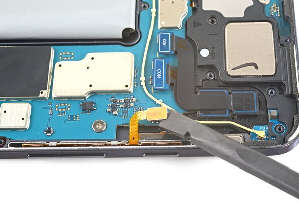
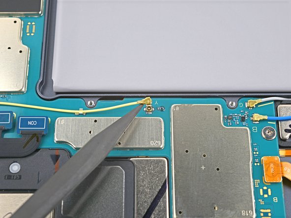
- Use the point of a spudger to carefully pry up and disconnect the bottom-right loudspeaker's yellow coaxial cable from the motherboard.
- Take care not to puncture the battery with your tool—a punctured battery may leak dangerous chemicals or cause a fire.
- During reassembly, these can be tricky to reconnect. One at a time, hold each connector in place over its socket and press down with the flat end of a spudger. The connector should snap into place.
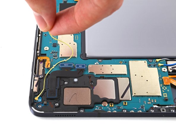
- Pull the coaxial cable away from the frame, making sure the cable is completely unthreaded from the motherboard.
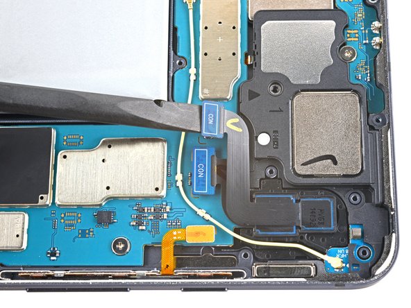
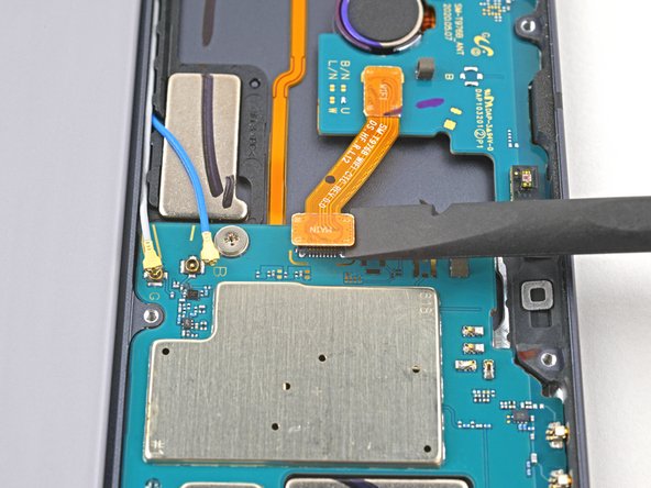
- Use the flat end of a spudger to pry up and disconnect the interconnect cable's press connector secured to the motherboard.
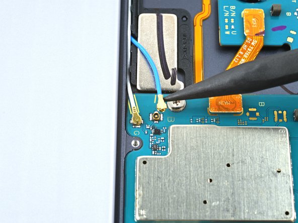
- Use the point of a spudger to carefully pry up and disconnect the top-right loudspeaker's blue coaxial cable from the motherboard.
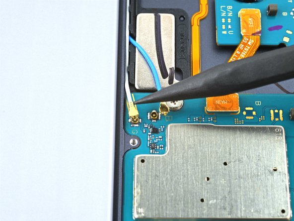
- Repeat this process for the white coaxial cable.
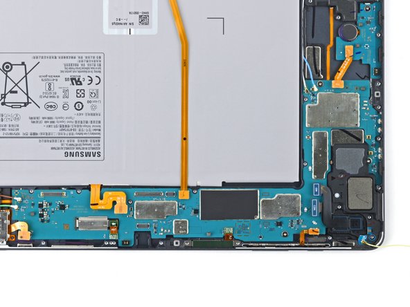
- Use a Phillips #00 screwdriver to remove the three 2 mm screws securing the motherboard to the frame.
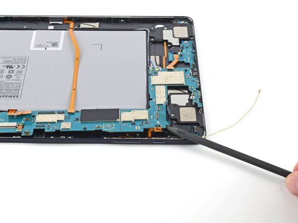
- Insert a spudger into a gap between the motherboard and the frame.
- Pry up with the spudger to release the motherboard from its clips.
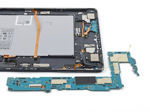
- Remove the motherboard.
- During reassembly, refasten the motherboard screws first to properly align it into place, then reconnect the cables.