Wahoo Elemnt Roam (WFCC4) Screen and Battery Replacement
ID: 152118
Description: As there is little to no information on how to...
Steps:
- The unit consists of 3 main parts:
- The bottom case, which holds the battery, USB charging port, as well as the rubber side buttons
- The top case, which holds the mainboard, LEDs, and the top rubber buttons
- The screen which is glued to the top case and connected to the mainboard via two ribbon cables on the left hand side of the device
- To soften the glue use a heat gun (at low heat) or hair dryer and heat up the edge of the top case
- Use a small metal prying tool to pry open the device. This will take time and patience. The device is glued together like a tank!
- Be careful not to rip it apart as you might damage the ribbon cables connecting the screen to the mainboard.
- The battery is sensitive to heat; try to direct the heat towards the sides to prevent the battery from being damaged or exploding.
- Use a plastic spudger to remove the two ribbon cables that connect the USB port and the battery from the mainboard
- To remove the connectors you simply have to lift them up perpendicular to the mainboard
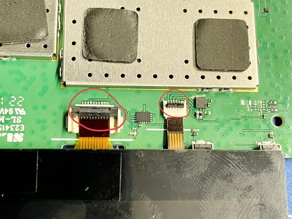
- There are two ribbon cables that connect the screen and LEDs to the mainboard
- Use a small pin / plastic spudger to lift up the black, plastic tabs that secure the ribbon cables in the connector (circled in red)
- Carefully pull the ribbon cables out of the connectors
- The mainboard is connected to the top of the case by four Torx 5 screws and held in place by two, small plastic guide pins in the top and bottom right corner (see arrows)
- Use a Torx 5 bit and remove all of the screws
- Ensure that you have removed the two ribbon cables connecting the screen and LEDs, before you remove the mainboard
- After removing the mainboard, pull out the two white rubber bars for the LED lights.
- Also keep track of the three small, plastic extensions for the top rubber buttons. They can easily fall out and they are tiny!
- The screen is glued securely to the top of the case
- Use a heatgun / hair dryer to soften the glue and use a small, thin prying tool to remove the screen from the top of the case
- Again, this will take a lot of time and patience. Also, there's a very high chance that the screen will not survive this procedure. So be sure that you want to replace it before attempting to remove it
- Remove the old glue from the top of the case and clean the surface
- Add fresh glue and insert the new screen
- Be careful not to use too much glue. The screen is a tight fit and excessive glue will squeeze out, messing up the screen and filling up the holes for the LED bar
- Install the two white rubber bars to the top of the case
- Be sure to add the three small, plastic extensions to the backside of the rubber buttons (red circle second picture). If you don't install these, the buttons won't work and you cannot add them later
- Guide the two ribbon cables for the LEDs and screen through the cable guides on the left side of the mainboard
- Ensure that the mainboard is positioned correctly and look out for the two guide pins in the top and lower right hand corners of the top case (see arrows)
- Use a Torx 5 screw driver to screw in the four screws, fastening the mainboard to the top of the case (red circles)
- Connect the two ribbon cables to the mainboard. Ensure that the black plastic tabs (red circles in the second picture), are in the up position before you insert the ribbon cables
- Push down the two black plastic tabs (red circles in the second picture), to secure the ribbon cables
- The battery is glued securely to the bottom of the case with double sided tape
- Use a plastic spudger to carefully pry the old battery from the case. This will take some time and patience, as the double sided tape is very strong
- Remove the amber kapton tape and snip off the two main connectors to the battery circuit board
- Dispose of the old battery in the right way and DO NOT throw it into the trash
- Be careful when working with the battery and connectors and avoid creating a short between the two connectors
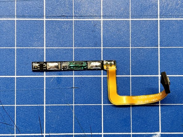
- Although the new battery comes with its own circuit board, we'll have to use the old one as an intermediary / extension
- Remove the remaining pieces of the old battery connectors from the two main pads. Be careful not to rip off the pads from the circuit board.
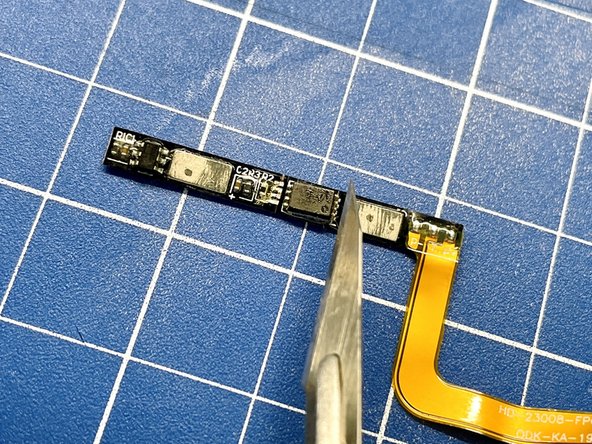
- To avoid any conflicts between the logic of the old battery's IC and the IC of the new one, we have to remove the old one. Remove the small IC from the circuit board using an exacto knife or similar
- Use a soldering iron and some soldering wick to remove the remaining solder from the pads for the IC
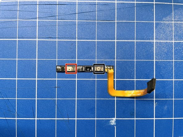
- Note The pad to the left of the IC (U2) is for the positive side, and the pad to the right of the IC is for the negative side (see last picture for correct orientation)
- We have to solder a bodge wire to create a permanent connection between the negative side of the old battery's circuit board and the ribbon cable.
- Solder a small enamelled copper wire to bridge the two center pads of the IC (red circles first picture)
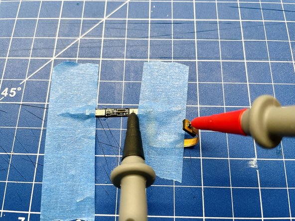
- Use a multimeter to check the connection between the negative side of the circuit board and the ribbon cable
- Add some solder to the positive and negative tabs of the board to prepare them for soldering later
- You can also add some solder mask to the bodge wire for extra protection
- Remove the kapton tape securing the new battery's circuit board
- Use a soldering iron to remove the attached wires from the circuit board's pads
- Use a soldering iron and some soldering wick to clean up the pads
- Add some fresh solder to the pads and solder two thin, flexible wires to the positive and negative tabs of the circuit board
- Please take note of the wires' orientation. As you'll have to wrap the wires around the battery to fit the battery and wires into the case, solder them at an angle to make your life easier
- Fold the new battery's circuit board over and inwards
- Use some kapton tape to secure the circuit board
- Lead the wires around the side of the battery and secure them with kapton tape as well
- Make sure the whole assembly is tightly packed and tidy to save space
- Use a multimeter to check for the battery's voltage to ensure the wires are connected correctly and that there's no short
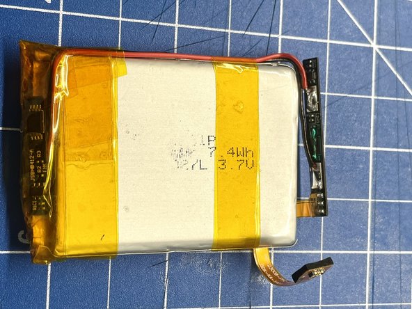
- Solder the positive and negative leads to the pads of the old battery's circuit board, which we prepared earlier
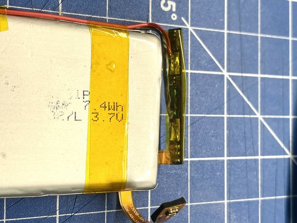
- Please take note of the circuit board's and the ribbon cable's orientation. The ribbon cable has to run under the battery and then wrap around it, to ensure proper orientation with the connector on the mainboard
- Wrap the circuit board in kapton tape and secure it closely to the battery, to create a tight and tidy package
- Use a multimeter to check for voltage at the ribbon cable's end points, to check for a proper connection
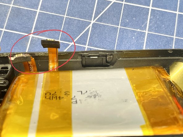
- Remove some material from the plastic tabs at the side of the bottom of the case to ensure that the new battery fits properly
- Please take note of the orientation of the battery. The battery ribbon cable must be located in the lower half of the case, right next to the ribbon cable to the USB connector
- This is a good time to connect the two halves of the case for a test fit to see that everything fits ok. If you need to squeeze too hard to get the two halves together, move the battery / cables / etc. to find a better fit
- When you're happy with the fit, add some (thin!) double sided tape to the bottom of the case to secure the battery.
- Reinstall the three plastic tabs for each of the side buttons.
- Note Without the tabs the buttons won't work and they do have an orientation. So ensure that they are installed correctly.
- Connect the two ribbon cables for the USB connector and the battery to the mainboard
- Press the Power button to test that the device starts correctly. Note: You'll have to directly press the small button on the left hand side of the mainboard to power up the device
- Connect the device to a USB charger, to test that the device charges correctly
- Note : GPS might not work at this stage. If you want to try it out, make sure the 4 pins on PCB are in contact with the the 4 bottom traces by pressing the two halves together firmly. Go under a clear sky.
- After you have tested the device successfully and confirmed that everything fits snug and tidy, you can glue the two halves back together
- Add some glue to the small lip of the bottom half of the case that connects to the top half and press both halves together
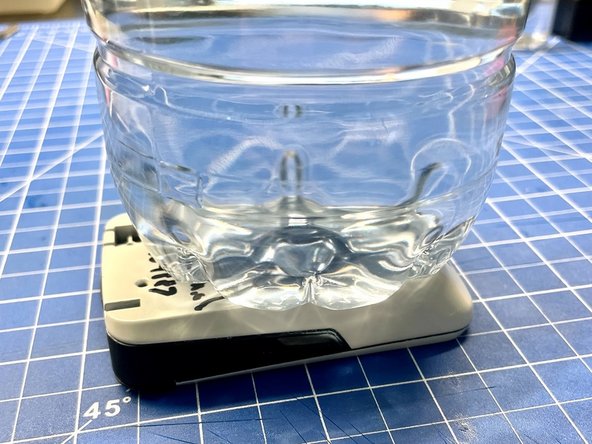
- The best way to put pressure on both halves evenly, is to put the device upside down and to add some weight (e.g. a water bottle) on the backside of the device
- Note I have used B-7000 glue to reassemble the device and it has worked well so far. The device will encounter all sorts of weather conditions and temperatures, so you need some flexible glue that can cope with those conditions
- Remove the screen protector from the replacement screen and test the device fully
- In case you're wondering about the grey/white case. I've used the opportunity to give the device a different color.