Google Pixel 3 XL Screen Assembly Replacement
ID: 152678
Description: This repair guide was authored by the iFixit...
Steps:
- Insert a SIM eject tool, bit, or a straightened paper clip into the small hole, located at the bottom edge of the phone.
- Press firmly to eject the tray.
- Remove the SIM tray from the phone.
- Heat an iOpener and apply it to the right edge of the back cover for a minute.
- A hair dryer, heat gun, or hot plate may also be used, but be careful not to overheat the phone—the display and internal battery are both susceptible to heat damage.
- While you wait, note the following areas on the back cover:
- Strong adhesive—there are large patches of adhesive near the bottom of the phone.
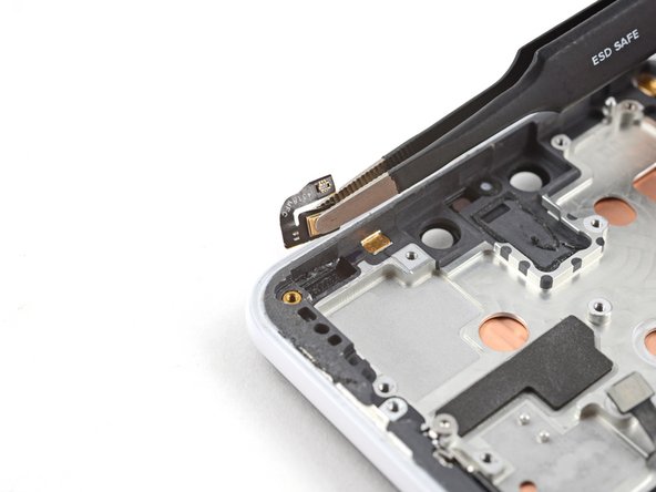
- Fingerprint sensor cable—be careful not to slice through the cable as you pry
- Apply a suction cup to the heated edge of the back cover, as close to the edge as possible.
- Pull up on the suction cup with strong, steady force to create a gap.
- Depending on the age of your phone, this may be difficult. If you are having trouble, apply heat to the edge and try again.
- Insert the point of an opening pick into the gap.
- Slide the opening pick along the right edge to slice through the adhesive.
- The adhesive gums up and becomes hard to slice once it cools. If that happens, re-apply heat to the edge to make slicing easier.
- Once you have sliced through the edge, leave an opening pick in the seam to prevent the adhesive from re-sealing.
- Apply a heated iOpener to the bottom of the back cover for a minute.
- Use an opening pick to slice around the bottom right corner and continue along the bottom edge of the phone.
- Work slowly as you slice around the corner to prevent the panel from cracking. If the slicing becomes hard, re-apply heat.
- Leave a pick in the edge to prevent the adhesive from re-sealing.
- Continue heating and slicing the remaining edges of the phone.
- Be careful as you slice along the left edge of the phone. If your pick feels like it's stuck near the top, you may have snagged the fingerprint sensor. Retract the pick out of the seam slightly and try again.
- Be sure to cut through the thick portions of adhesive near the bottom and right edge of the phone.
- Gently pry up the right edge of the back cover.
- Use an opening pick to slice through any remaining adhesive along the edges.
- Swing the right edge of the back cover upwards and rest the flipped panel along the left side of the phone.
- Be sure to maintain slack on the fingerprint sensor cable and prevent it from being pinched.
- During reassembly, this is a good point to power on your phone and test all functions before sealing it up. Be sure to power your phone back down completely before you continue working.
- During reassembly, follow this guide to install custom-cut adhesives for your back cover.
- If you replaced the fingerprint sensor, you'll need to use this software tool to make the phone recognize the new sensor.
- User tweezers to carefully peel up the yellow tape over the fingerprint sensor connector.
- Use the point of a spudger to carefully flip up the black lock bar on the fingerprint sensor's ZIF socket.
- Grasp the cable's tab with your fingers or tweezers and gently walk the flex cable out of the socket.
- To prevent shorting, be careful not to touch the metal contacts on the flex cable with your tweezers.
- Remove the back cover.
- Follow this guide to correctly apply new back cover adhesive.
- Remove the following four T3 screws securing the metal cover bracket:
- Three 4 mm long screws
- One 3 mm long screw
- Throughout this repair, keep track of each screw and make sure it goes back exactly where it came from.
- Insert the flat end of a spudger underneath the top right edge of the metal bracket and pry up to loosen it.
- Remove the metal cover bracket.
- Use the point of a spudger to pry up and disconnect the battery connector from its socket.
- Do not use metal tools to to disconnect the battery, or you will risk shorting the battery.
- Bend the battery cable such that the connector will not accidentally touch the socket.
- Remove the five T3 screws securing the motherboard shield:
- Three 4 mm long screws
- Two 3 mm long screws
- Remove the motherboard shield.
- Remove the three 3 mm long T3 screws securing the front camera bracket.
- Remove the front camera bracket.
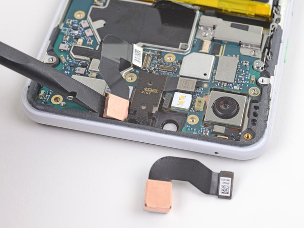
- Use the point of a spudger to carefully pry up and disconnect the cameras from their motherboard sockets.
- Be very careful not to dislodge the small surface-mounted components surrounding the sockets.
- The cameras are lightly adhered in place.
- Use the flat end of a spudger to pry up and loosen the camera modules from their recess.
- Remove the front-facing cameras.
- Remove the 4 mm long T3 screw securing the top-right corner of the loudspeaker.
- Removing this screw will give you slightly more wiggle room when removing the motherboard.
- Remove the two 3 mm long T3 screws securing the button array connector bracket.
- Remove the button array connector bracket.
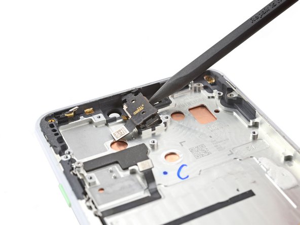
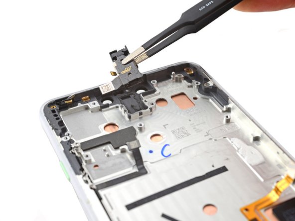
- Use the point of a spudger to pry up and disconnect the earpiece connector from its motherboard socket.
- Carefully remove the connector pad surrounding the earpiece socket.
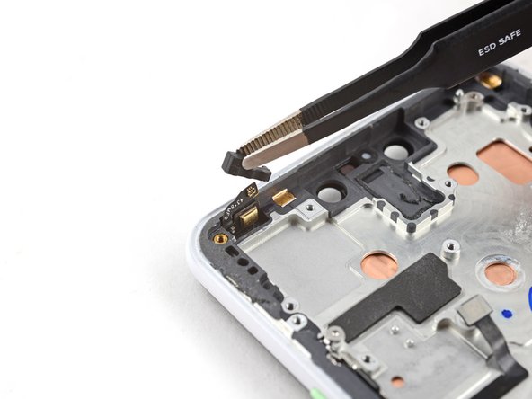
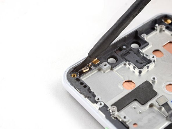
- Use the point of a spudger to pry up and disconnect the following:
- Microphone connector
- Button array connector
- Earpiece connector (should already be disconnected)
- Use the point of a spudger to pry up and disconnect the following:
- Charging coil connector
- Left squeeze sensor connector
- Display connector
- Right squeeze sensor connector
- Loudspeaker connector
- USB-C port connector
- Remove the two 3 mm long T3 screws securing the motherboard.
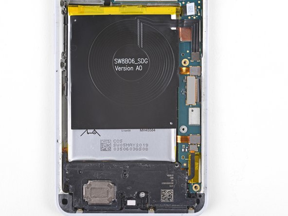
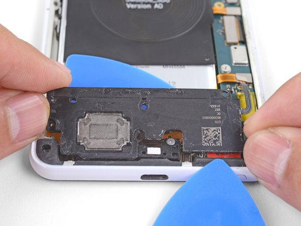
- Insert the point of a spudger underneath the motherboard, near the rear-facing camera module.
- Pry up gently to loosen the motherboard from its recess.
- If the motherboard is not budging, make sure you have disconnected all the connectors.
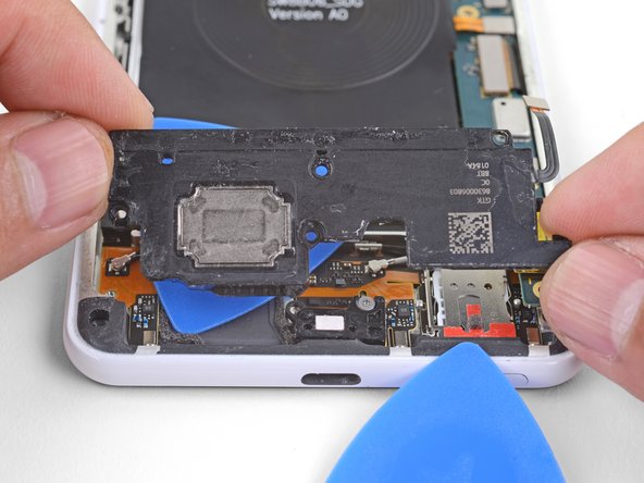
- The motherboard has to squeeze past the earpiece speaker cable. If too much pressure is put on the earpiece cable, the earpiece speaker will pop open. You can prevent this by pressing on the earpiece module with a finger while you maneuver the motherboard out.
- If the earpiece speaker pops open (as shown in the third photo of this step), carefully align and press the module back in place.
- Don't attempt to remove the motherboard from the phone. It's still attached to the phone.
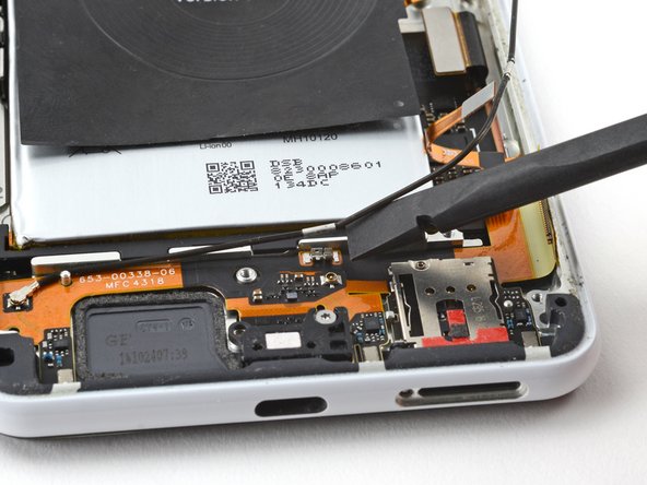
- While you perform this step, take care to keep slack on the antenna cables attached to the bottom leg of the motherboard.
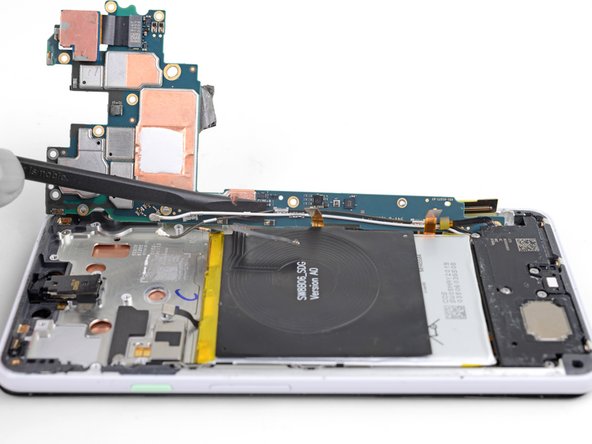
- Lift the top half of the motherboard slightly to clear the board from its recess.
- Twist the left edge of the board over and out of the phone and rest the board on the right edge of the phone.
- Use the flat of a spudger to gently pry up and loosen the black and white antenna cables from their motherboard clips.
- The cables are fragile and the clips hold onto them tightly. Be patient and pry as close to the base of the clips as possible.
- Remove the motherboard.
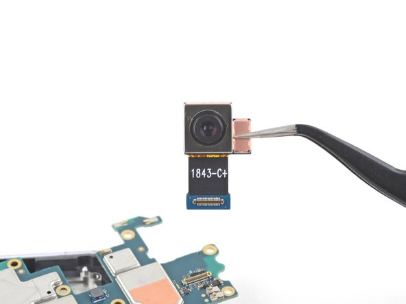
- If you are installing a new motherboard, follow these instructions to transfer the rear-facing camera:
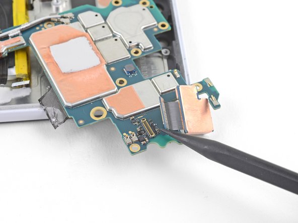
- Use the point of a spudger to pry up and disconnect the rear-facing camera from its motherboard socket.
- Remove the rear-facing camera and transfer it to your replacement motherboard.
- Compare your new replacement part to the original part. You may need to transfer remaining components or remove adhesive backings from the new part before installing.
- If you have already removed the motherboard, the top right loudspeaker screw will already be removed.
- Remove the following four T3 screws securing the loudspeaker:
- Three 4 mm long screws
- One 3.9 mm long screw
- Insert the point of an opening pick under the bottom right corner of the loudspeaker.
- Slide the pick in to loosen the right side of the loudspeaker.
- Insert the point of an opening pick under the top edge of the loudspeaker, below the battery.
- Slide the opening pick in to slice through the adhesive gasket under the loudspeaker.
- Lift the loudspeaker out slowly and pull it away from any remaining adhesive.
- Remove the loudspeaker.
- Before you reinstall the loudspeaker, you may want to remove any residual adhesive from the frame and place new adhesive.
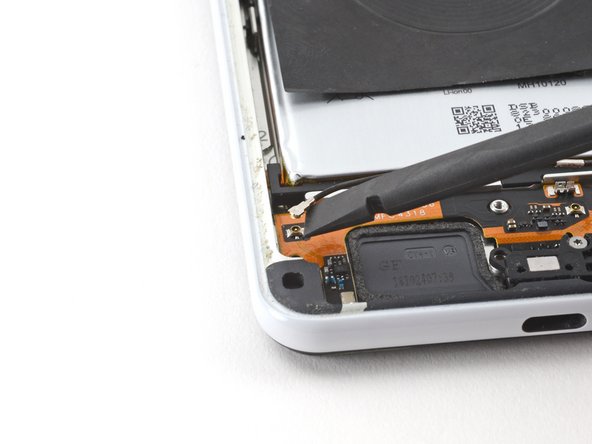
- Use the flat end of a spudger to pry up and disconnect the white coaxial cable connector from the charging assembly.
- Remove the white coaxial cable from the phone.
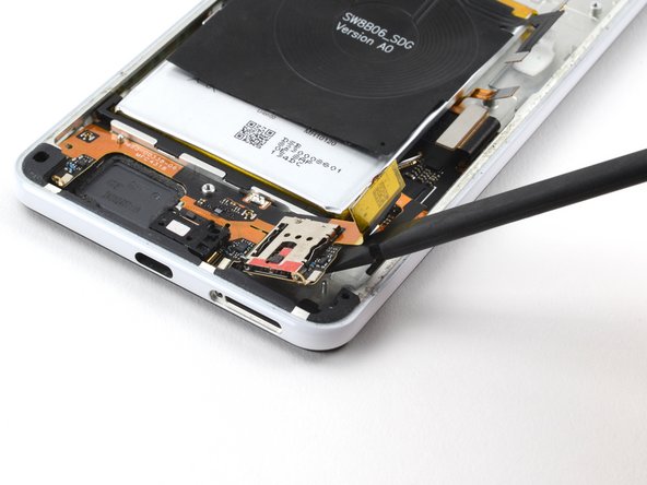
- Use the flat end of a spudger to pry up and detach the black coaxial cable from its clip on the charging assembly.
- Use the flat end of a spudger to pry up and disconnect the black coaxial cable connector from the charging assembly.
- Remove the black coaxial cable from the phone.
- Use a T3 Torx screwdriver to remove the three 2.4 mm screws securing the charging assembly to the frame.
- Use a T3 Torx screwdriver to remove the 3.9 mm screw securing the USB-C port bracket to the frame.
- If you haven't removed the SIM card tray from the phone, do so now. The charging assembly cannot be removed without removing the tray.
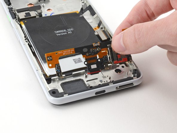
- The right side of the charging assembly is secured to the frame by a peg adjacent to the SIM card reader.
- Slide the flat end of a spudger under the right side of the charging assembly to detach it from the frame.
- The left side of the charging assembly is secured to the frame by a peg and light adhesive.
- Insert the flat end of a spudger under the left side of the charging assembly.
- Pry up and detach the left side of the charging assembly from the frame.
- The USB-C port is secured to the frame by a red gasket. You may need to move the charging assembly back and forth to detach the assembly from the frame.
- Remove the charging assembly from the frame.
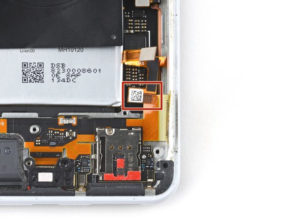
- During reassembly, make sure the right squeeze sensor cable is situated above the USB-C port cable.
- The right squeeze sensor cable is adjacent to the bottom right corner of the battery.
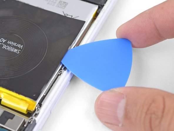
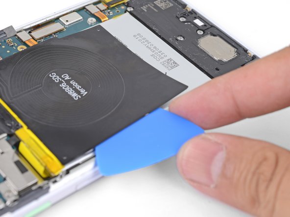
- Insert the point of an opening pick underneath one edge of the charging coil.
- Slide the pick along the edge to loosen the adhesive.
- Slice as deep as you can while taking care not to puncture the battery's surface.
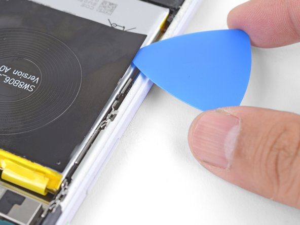
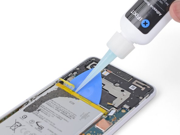
- Tilt the edge you have been slicing upwards.
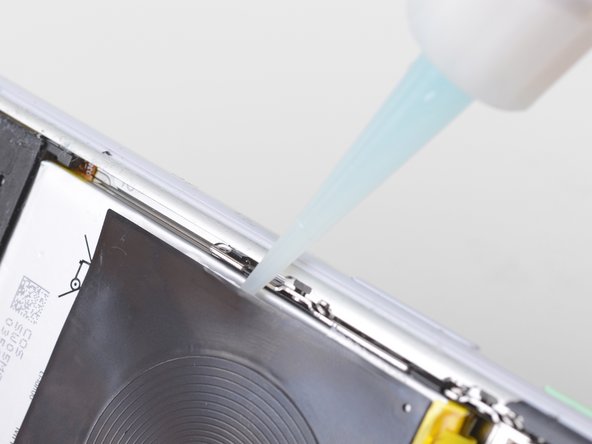
- While holding the phone in a tilted position, apply a few drops of adhesive remover or high concentration isopropyl alcohol along the edge.
- Keep the phone in that position for a minute or two to allow the adhesive to soften.
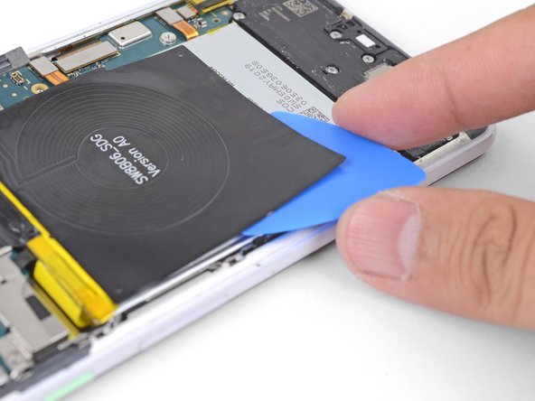
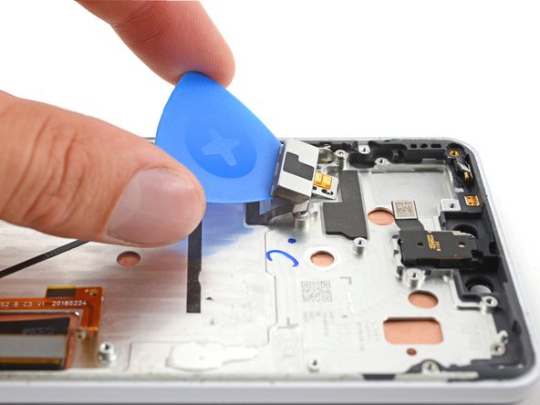
- Insert the flat end of an opening pick underneath a corner of the charging coil.
- Push the pick slowly and firmly under the coil to loosen the adhesive.
- The adhesive is mostly around the perimeter of the wireless coil. Use the opening pick to slowly slice through the adhesive.
- If the adhesive feels difficult to slice through, tilt the phone up and apply a few more drops of adhesive remover.
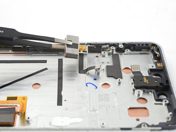
- Remove the wireless charging coil.
- To install a replacement coil:
- Use isopropyl alcohol and a lint-free cloth to clean off the battery surface of any adhesive residue. Be very careful not to puncture the battery.
- Connect the wireless coil connector to its motherboard socket. This ensures that the coil is properly aligned.
- Peel off any adhesive backing on the replacement coil.
- Lay the coil on top of the battery and firmly press it into position.
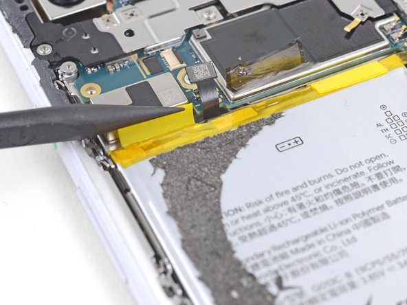
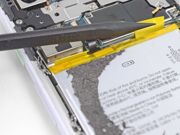
- Carefully slide the point of a spudger underneath the yellow battery pull tabs folded along the top edge of the battery.
- Separate the pull tabs from the battery.
- There are steep, sharp edges near the top of the battery, that can easily break the adhesive strip as it's being pulled out.
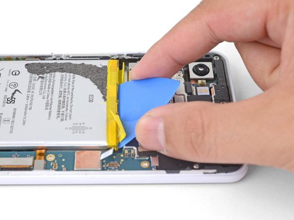
- Insert the flat end of an opening pick into the gap above the battery, behind a yellow pull tab.
- Wedge the pick firmly underneath the battery. The pick will serve as a buffer for the adhesive strip as well as a prying point.
- Pull on the yellow adhesive pull tab with slow steady force. Try your best to pull it as shallow of an angle (vs. straight up) as possible.
- As you pull on the adhesive tab, maintain pressure on the opening pick to wedge it underneath the battery as much as possible.
- If the adhesive feels stuck, you can apply a few drops of adhesive remover or high concentration isopropyl alcohol into the gap to help loosen the battery. Doing this will most likely loosen both strips at once.
- Repeat the process with the second adhesive pull tab.
- Remove the battery.
- Do not reuse the battery after it has been removed, as doing so is a potential safety hazard. Replace it with a new battery.
- To install a replacement battery:
- Use isopropyl alcohol and a lint-free cloth to remove any remaining adhesive from the battery well.
- Temporarily re-connect the battery connector to its motherboard socket. This ensures that the battery will be properly aligned.
- Apply stretch release adhesive strips, double-sided tape, or pre-cut adhesive strips to the battery well.
- Lay the battery in the phone and press it firmly in place.
- Disconnect the battery connector from its motherboard socket and resume reassembly.
- Insert an opening pick between the frame and the long edge of the vibrator.
- Slide the pick underneath the vibrator to separate the adhesive.
- If you're having trouble separating the adhesive, apply a heated iOpener to the vibrator for one minute.
- Use tweezers, or your fingers, to remove the vibrator.
- The earpiece speaker is lightly adhered to the frame.
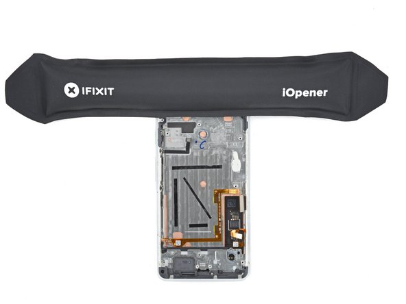
- Heat an iOpener and apply it to the top edge of the device for two minutes.
- Insert the tip of a spudger between the frame and the long edge of the earpiece speaker.
- Pry up with the spudger to separate the adhesive.
- Remove the earpiece speaker.
- The microphone assembly is lightly adhered to the frame.
- Heat an iOpener and apply it to the top left of the device for two minutes.
- Use tweezers to remove the rubber bracket between the microphone assembly and its recess in the frame.
- Insert a halberd spudger between the microphone assembly and the perimeter of the frame.
- Slide the halberd spudger downward and pry towards the battery to separate the adhesive.
- Use tweezers, or your fingers, to remove the microphone assembly.
- You're now left with the screen assembly.