Vitamix VM0102D Teardown
ID: 152912
Description: My wife was using our Vitamix and it started...
Steps:
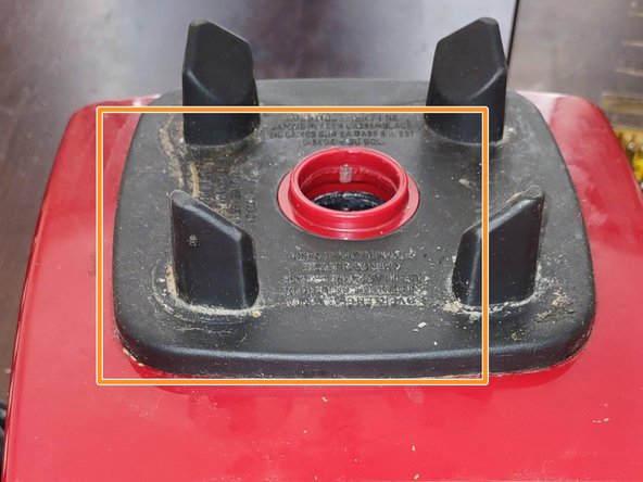
- To get the case open we pull off the rubber top
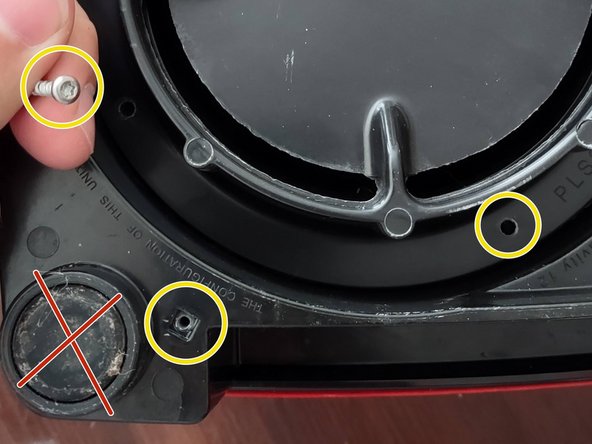
- Remove 4x Philips 2 screws. These are aggressive pitch screws for going into plastic
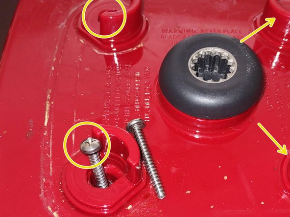
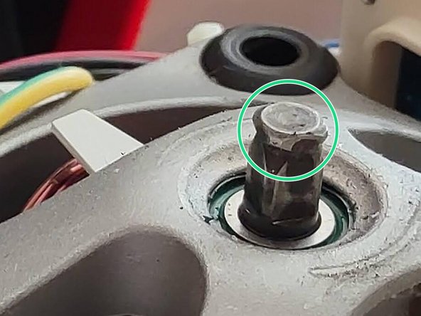
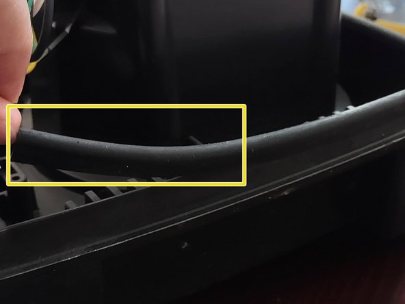
- This rubber and metal collar connects the motor shaft to the blender. It keeps the plastic top on the black base and is held in place with a hex 5 set screw with a head.
- There is also a silicon plug that sealed the access port to keep liquid out of the motor if it spills (or to prevent tampering)
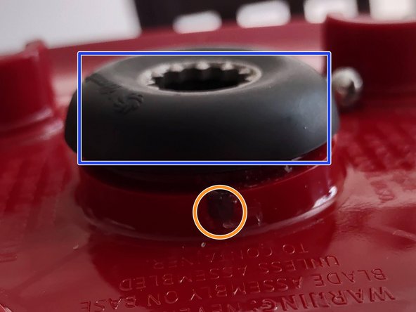
- Look for the small arrow on the black collar to line up the hex nut to the access port at the back of the Vitamix
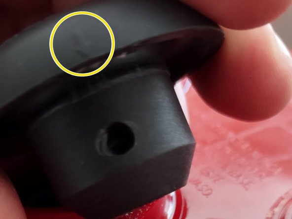
- The H5 hex nut can not be fully removed. The access port is too small for the head of the screw to fit through. Gentle pressure up on the black rubber will lift it off as the hex nut is backed out past the corner lip of the motor's notched shaft.
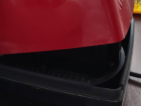
- Lift the top off the base. there are no directional hooks, only 4 rubber bumpers, one on each side, that provide friction as you pull.
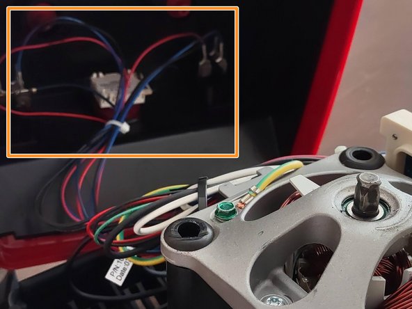
- There are wires connected to the front of the unit. They are long making this easy but don't put extra strain on them.
- My Project did not require any further teardown but now that you are in, most steps should be obvious.
- Be careful you don't loose any of the 4x rubber edges on the bottom 1/2
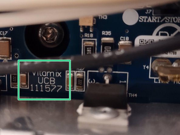
- The main board had a label of "Vitamix UCB 111577"
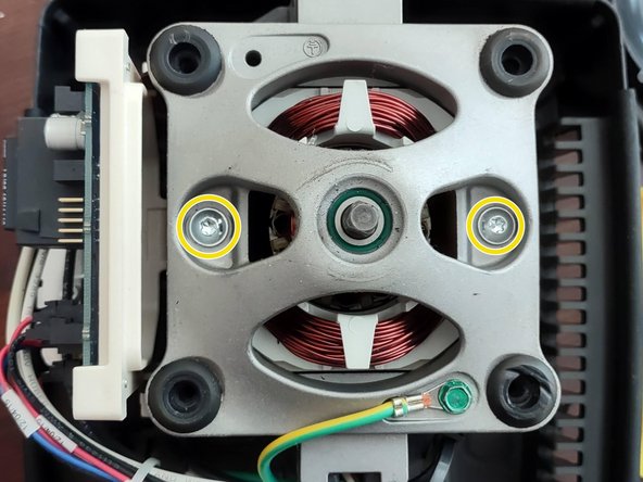
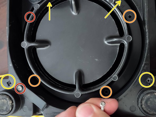
- From the looks of it there are two large Phillip's screws that hold the motor assembly in place.
- After taking the bottom apart (next steps) you are able to see the other end of these screws holding the whole structure together. I did not remove this assembly. Proceed at your own risk.
- The next few steps can be taken independantly from steps 1-5. These steps begin on the underside and access the brushes of the motor.
- There are no screws underneath the rubber feet
- Using Torx 10 remove 4x power cord holders around the middle. There is one located out the back that can be left alone.
- Also remove the 4x Torx 10 screws in the channel the power cord sits in. These screws penetrate 2 layers then seat into the plastic housing.
- Simply lift the first layer out.
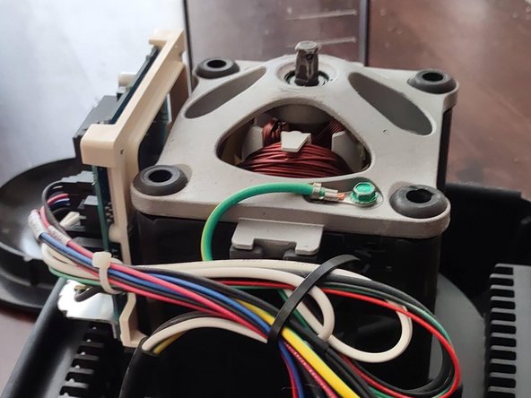
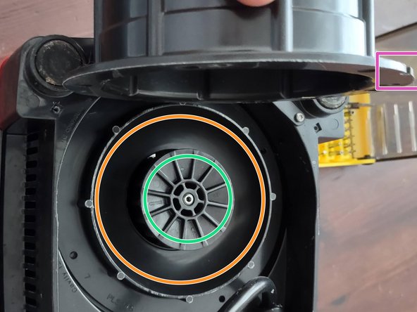
- The Motor fan sits inside the bowl of the 2nd layer
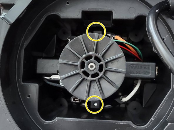
- The concave bowl is the 2nd layer and can be pulled up past the fan marked in green
- Both the 1st and 2nd layers have a small key hole to ensure proper placement when re-assembling
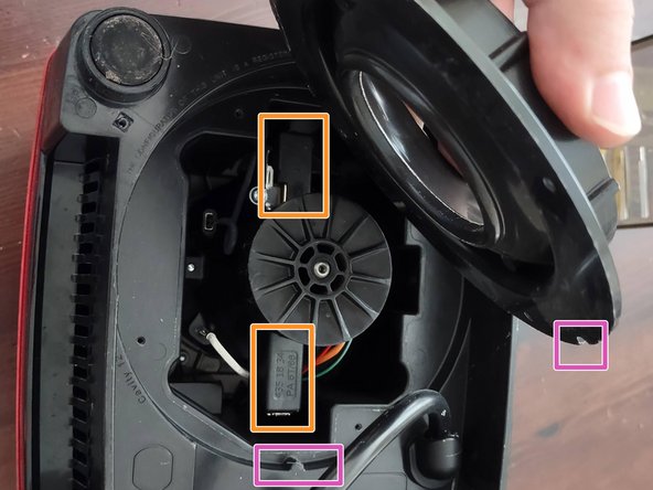
- After pulling out the cupped layer you have access to the two brush fixtures.
- This photo also shows the female and male key slots in layer 2 and the base
- I did not disassemble any portion of the underside and do not know how to replace the brushes. it may require complete disassembly of the electric motor. You are able to see one screw on one of the brush pads however.