Pentax ZX-5n Mirror Drive Lever Replacement
ID: 152953
Description: A common failure of the Pentax ZX-5n is the...
Steps:
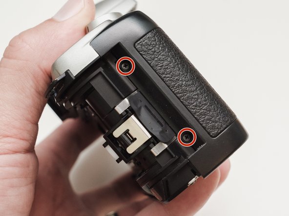
- Push down on the screw to depress the spring loaded hinge and release the door.
- Remove six 5.3 mm #00 screws.
- Remove one 3.4 mm #00 screw.
- The short screw has a machine thread and screws into the plate underneath. The rest screw into the plastic body.
- Remove three 5.3 mm #00 screws (the bottom-most screw is not always present).
- Remove one 7.3 mm #00 screw.
- Remove the remote trigger cover.
- Remove one 3.4 mm #00 screw.
- Remove two 5.3 mm #00 screw.
- Gently lift up on the flash housing to help remove the cover if necessary.
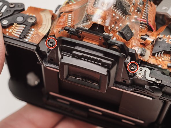
- Remove two 3.9 mm #00 screws.
- Slide the eye cup up and off to access the screws underneath.
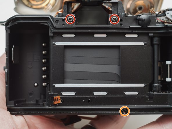
- Remove two 5.3 mm #00 screws by the eyepiece.
- Remove one 6.8 mm #00 screw in the battery compartment.
- Remove one 7.0 mm #00 screw near the take up spool.
- Lift the cover so it is just free of the body. It is still attached by several wires.
- Use a 1kΩ-10kΩ resistor to discharge the capacitor. Place the resistor between the blue wire, exposed in the previous step, and ground.
- The flash capacitors store energy at a very high voltage. Failing to discharge the capacitors properly could result in personal injury and/or damage to the camera.
- Unsolder one green wire.
- Unsolder one blue wire.
- Unsolder one brown wire.
- Unsolder one black wire.
- Unsolder one black wire.
- Pull black wire out from its routed location.
- Unsolder flex connector
- Be careful not to overheat the flex circuit. Work in short durations. Allow for cool downs in between if necessary.
- Some repairs can be performed with the top cover still connected but the flex connection is fragile and easily damaged.
- De-solder the indicated joints. Use a solder sucker on the tabbed connections.
- Pull the black wire from the battery flex to get more slack in the connection to the top cover.
- Be careful not to overheat the flex circuit. Work in short durations. Allow for cool downs in between if necessary.
- Use a solder sucker to de-solder the four posts from the flex circuit.
- This is the most difficult part of the repair. Patience and persistence are required.
- Be careful not to overheat the flex circuit. Work in short durations. Allow for cool downs in between if necessary.
- Unsolder film advance motor connections.
- Unsolder sprocket counter connections.
- Unsolder power and ground connections.
- Unsolder panorama switch connections.
- Be careful not to overheat the flex circuit. Work in short durations. Allow for cool downs in between if necessary.
- Remove one 4.3 mm #00 screw.
- Gently pry up the plastic carrier under the flex circuit. It may catch slightly on the battery contact tab.
- Pay close attention to the connections around the four through-hole posts as you lift the flex. Make sure that no solder is left over and that it pulls away freely.
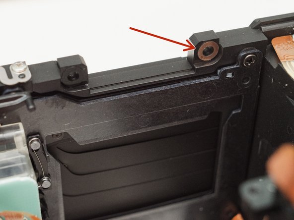
- This metal tab is lightly held in place with lacquer and can easily come loose. Keep an eye on it.
- Remove one 3.3mm #00 screw.
- Remove one 3.9 #00 screw.
- De-solder the red wire.
- Peel off the black tape. Leave it attached to the wires.
- Gently peel the flex circuit from the surface of the capacitor.
- There may be additional adhesive underneath the larger capacitor.
- Lift the two capacitors and the flash PCB out as a single unit.
- The double sided tape used to secure the capacitors can be softened with isopropyl alcohol if necessary.
- Remove two 3.4 mm #00 screws. Remove the plate holding the contacts in place.
- Peel tape from the plate. Leave the tape attached to the flex circuit.
- Remove the flex circuits from their retaining studs.
- Remove one 3.3 mm #0 countersunk screw.
- Remove one 3.9 mm #0 shoulder screw.
- Remove four 3.3 mm #00 screws.
- Pull a little slack through the housing on this flex cable.
- Pop the plate off its posts, rotate slightly clockwise and pull gently through the loosened flex cable.
- To the camera tech that left me a happy little note...I see you.
- It's best to remove these parts now so they don't fall out later on in the repair.
- Remove one 3.8 mm #00 screw.
- De-solder the connections.
- Lift the flex off the retaining studs.
- Be careful not to overheat the flex circuit. Work in short durations. Allow for cool downs in between if necessary.
- Remove two 5.3 mm #0 screws.
- Remove two 7.4 mm #0 screws.
- Remove one 8.3 mm #0 screw.
- Remove one 3.3 mm #00 screw. The metal bracket will be loose and should be removed as well.
- Push the front housing block slightly up then lift the left side up and away from the housing.
- Proceed slowly and watch for any components that are catching. The right side is still attached by a large flex cable.
- There may be shims at the mounting points of the front housing block.
- Note the positions and remove if loose.
- De-solder the black wire.
- Remove four 3.7 mm #00 screws.
- Detach the buzzer from its mounting posts. Use isopropyl alcohol to soften the lacquer if necessary.
- Grab the motor and gently wiggle the plate loose.
- If it feels stuck, move the sliding plate down, towards the bottom of the camera
- Slide the green and yellow gears off of their shafts.
- The broken part. If the small tip is completely detached, locate it and remove it from the camera before reassembly.
- Place a finger over the larger spring to keep it in place as you slide off the lever.
- Use tweezers to place the spring arm on the lower side of the post and tension the lever.
- Place the long spring arm on the left side of the mirror pivot.
- Check proper function of the mirror by moving the bottom arm of the lever back and forth. The mirror should rest in the upper position but be able to move up and down.
- If using a 3D printed replacement part, remove the tensioning spring and temporarily install the green gear Turn it counterclockwise through the entire mirror cycle. There should be no binding of the gear at any point. Adjust the drive lever as necessary until it moves through the entire cycle without resistance.
- When placing the gears, line up the two indicated holes. The gears must be in sync for the shutter and mirror to work properly.
- Turn them back and forth a few degrees to make sure they are fully seated.
- Aperture set lever spring. Note this part for installation of the mirror motor assembly.
- Disengage latch so the slide bar can move freely.
- Move the slide bar about half way down its total travel.
- Let the latch snap back into place so the slide bar is held in the new position.
- This ensures that the aperture set lever spring couples properly with the slide bar during reassembly.
- Place the left side first. Then swing the right side in, coming up and under the spring loaded lens release.
- Rotate the grey gear downward until the mirror is in the charged/down position.
- Push the shutter charge lever upward. You should see the shutter blades move as you do this.
- The second picture shows the shutter in the charged position. It may already be in this position and not need charging.
- Gently place the front assembly block. Work it into place until the back of the block is flush to the back of camera.
- Proceed with the rest of the re-assembly, following the guide in reverse.