iPhone 14 Logic Board Replacement
ID: 154852
Description: Use this guide to remove and replace the logic...
Steps:
- Insert a SIM card eject tool into the small hole in the SIM card tray, located on the volume button edge of the iPhone.
- Press firmly to eject the tray.
- Remove the SIM card tray from the iPhone.
- When reinserting the SIM card, make sure it's in the proper orientation inside the tray.
- A thin rubber gasket around the SIM tray provides water and dust protection. If this gasket is damaged or missing, replace the gasket or the entire SIM tray to protect your iPhone's internal components.
- Power off your iPhone before beginning disassembly.
- Use a P2 pentalobe screwdriver to remove the two 6.8 mm‑long screws on either side of the charging port.
- If inserted too far, an opening pick can damage your device. Follow this step to mark your pick and prevent damage.
- Measure 3 mm from the tip and mark the opening pick with a permanent marker.
- You can also mark the other corners of the pick with different measurements.
- Alternatively, tape a coin to a pick 3 mm from the tip.
- If your iPhone has a cracked screen, keep further breakage contained and prevent bodily harm during your repair by taping over the glass.
- Lay overlapping strips of clear packing tape over the iPhone's screen until the whole face is covered.
- Wear safety glasses to protect your eyes from any glass shaken free during the repair.
- If you can't get the suction cup to stick in the next few steps, fold a strong piece of tape (such as duct tape) into a handle and lift the screen with that instead.
- If all else fails, you can superglue the suction cup to the screen.
- For easier screen removal in the next steps, note the following:
- There's a plastic bezel on the underside of the screen. Your opening pick will go underneath this bezel.
- There's a seam between the plastic bezel and the display panel. Don't insert your pick here or you'll separate the two.
- Sometimes the display panel separates from the bezel before you even get a chance to insert a pick. This may be unavoidable depending on the condition of the adhesive.
- Use a hair dryer or heat gun to heat the bottom half of the screen until it’s slightly too hot to touch. This softens the adhesive securing it.
- Improper use of a heat gun can destroy the display and/or battery—review this guide for instructions. To prevent screen damage, keep your heat source moving rather than focused on one spot.
- For tips on using a hair dryer to soften adhesive, check out this guide.
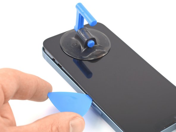
- Apply a suction handle near the bottom edge of the screen.
- Pull up on the suction handle with firm, constant pressure to create a slight gap under the screen.
- The adhesive holding the screen in place is very strong. If you're having a hard time, apply more heat, and gently rock the screen up and down to weaken the adhesive until you create enough of a gap to insert your tool.
- Pull up on the suction cup with firm, constant pressure to create a slight gap between the screen and the frame.
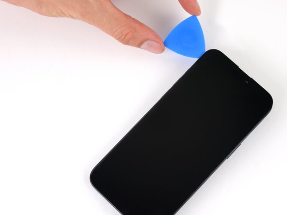
- Insert an opening pick beneath the screen and its plastic bezel.
- Make sure to insert the opening pick under the thick plastic bezel to avoid damaging your screen. You should see a visual gap, and the pick shouldn't catch on anything. If you can't see the gap, you'll need to pull the screen up more.
- If you can't create a gap, apply more heat to the edge and try again.
- Don't insert your opening pick deeper than 3 mm along the bottom edge.
- Slide your pick back and forth along the bottom edge to separate the adhesive.
- Leave your pick inserted in the bottom right corner to prevent the adhesive from re-sealing.
- Heat the right edge of the iPhone (the edge with the power button) until the screen is slightly too hot to touch.
- Slide the opening pick around the bottom right corner of the iPhone to separate its adhesive.
- Continue sliding up the right edge of the iPhone until you reach the top right corner.
- Don't insert your pick more than 3 mm, as you may damage internal components.
- Leave the pick in the top right corner before continuing.
- Heat the top edge of the iPhone until the screen is slightly too hot to touch.
- Don't insert your pick deeper than 3 mm along the top edge.
- Slide your pick around the top right corner and along the top edge to release the two clips and adhesive securing it.
- Heat the left edge of the iPhone until the screen is slightly too hot to touch.
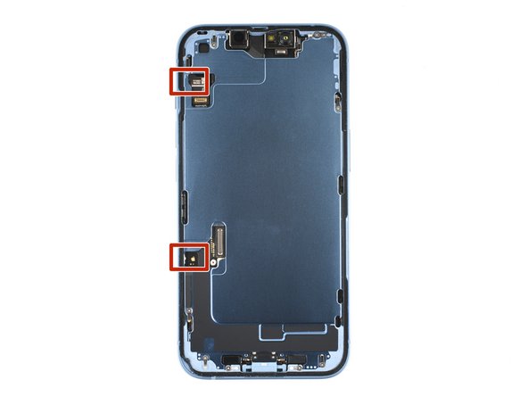
- There are delicate cables along the left edge of your iPhone. Don't insert your pick deeper than 2 mm here, as you may damage the cables.
- Rotate your pick around the top left corner of the screen.
- Slide your pick to the bottom left corner of the screen to separate the adhesive.
- If you're having trouble separating the adhesive, reheat the left edge.
- Remove your suction handle from the screen.
- Rotate your iPhone so the right edge faces you.
- Open your iPhone by swinging the screen up from the right side, like the front cover of a book.
- Lean the screen against something to keep it propped up while you're working on the phone.
- If you don't have anything at hand to lean the screen against, your suction handle can do the trick.
- During reassembly, lay the screen in position, align the clips along the top edge, and carefully press the top edge into place before snapping the rest of the screen down. If it doesn't click easily into place, check the condition of the clips around the perimeter of the screen and make sure they aren't bent.
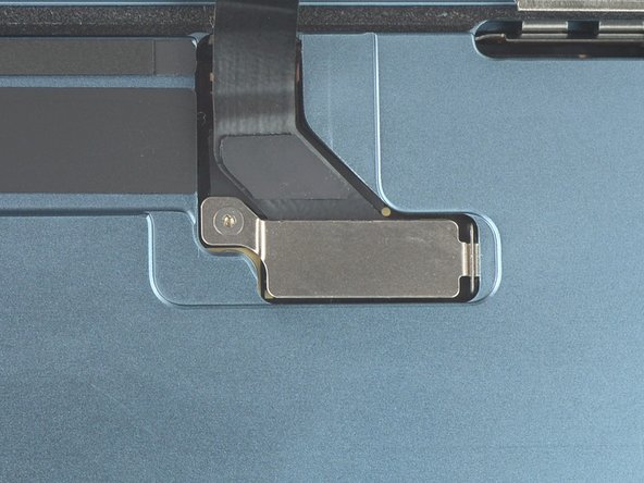
- Use a Y000 screwdriver to remove the 0.9 mm-long screw securing the display connector bracket.
- Throughout this repair, keep track of each screw and make sure it goes back exactly where it came from to avoid damaging your iPhone.
- During reassembly, this is a good point to power on your iPhone and test all functions before you seal the screen in place. Be sure to power your iPhone back down completely before you continue working.
- Grasp the screw hole end of the connector bracket with a pair of tweezers.
- Lift the bracket slightly to loosen the latch on the other edge.
- Remove the display connector bracket.
- During reassembly, make sure the bracket latches properly.
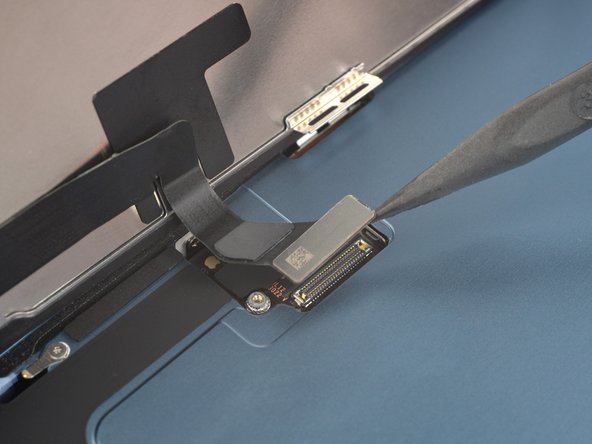
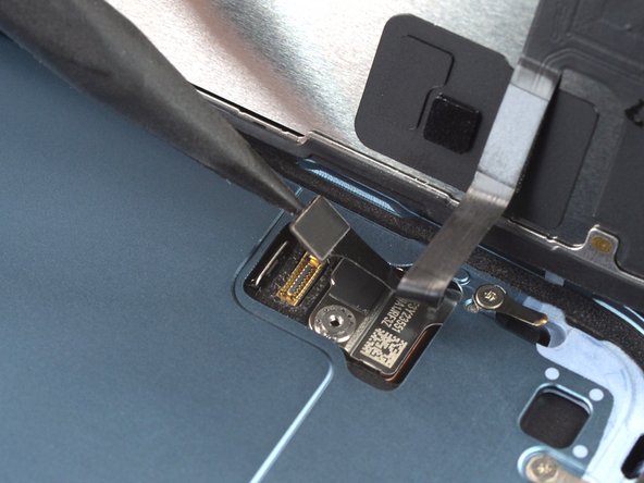
- Use the pointed end of a spudger to disconnect the display cable by prying the connector straight up from its socket.
- To re-attach press connectors like this one, carefully align and press down on one side until it clicks into place, then repeat on the other side. Do not press down on the middle. If the connector is misaligned, the pins can bend, causing permanent damage.
- Use a Y000 screwdriver to remove the 0.9 mm-long screw securing the front sensor connector bracket.
- Grasp the screw hole end of the connector bracket with a pair of tweezers.
- Lift the bracket slightly to loosen the latch on the other edge.
- Remove the front sensor connector bracket.
- During reassembly, make sure the bracket latches properly.
- Use the pointed end of a spudger to disconnect the front sensor cable by prying the connector straight up from its socket.
- Remove the screen.
- Apply new adhesive where it's necessary after cleaning the relevant areas with isopropyl alcohol (>90%).
- During reassembly, pause here if you wish to replace the screen adhesives.
- If your iPhone has a cracked rear glass, keep further breakage contained and prevent bodily harm during your repair by taping over the glass.
- Lay overlapping strips of clear packing tape over the iPhone's rear glass until the whole face is covered.
- Wear safety glasses to protect your eyes from any glass shaken free during the repair.
- If you can't get the suction cup to stick in the next few steps, fold a strong piece of tape (such as duct tape) into a handle and lift the rear glass with that instead.
- If all else fails, you can superglue the suction cup to the rear glass.
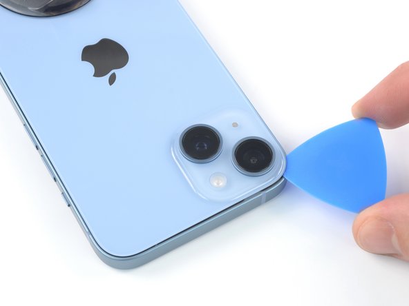
- Use a hair dryer or a heat gun to heat the bottom edge of the iPhone until the rear glass is slightly too hot to touch.
- Never leave your heat gun in one spot for an extended period of time.
- Apply a suction handle to the bottom edge of the rear glass, while avoiding the very edge of the glass.
- Pull up on the suction cup with firm, constant pressure to create a slight gap between the rear glass and the case.
- Insert an opening pick into the gap.
- The adhesive holding the rear glass in place is very strong; creating this initial gap takes a significant amount of force. If you're having a hard time opening a gap, apply more heat, and gently rock the rear glass up and down to weaken the adhesive until you create enough of a gap to insert your opening pick.
- Heat the left edge of the iPhone until the rear glass is slightly too hot to touch.
- Slide the opening pick around the lower left corner and up the left edge of the iPhone, slicing through the adhesive holding the rear glass in place.
- Don't insert your pick more than 3 mm, as you may damage internal components.
- There's a delicate cable along the right edge, next to the volume up button. Don't insert your pick here, as you may damage the cable.
- Heat the right edge of the iPhone (the edge with the volume buttons) until the rear glass is slightly too hot to touch.
- Re-insert your pick at the bottom edge of the iPhone, and slide it up the right side to continue separating the adhesive.
- Don't insert your pick more than 3 mm, as you may damage the charging coil cable.
- Heat the top edge of the iPhone until the rear glass is slightly too hot to touch.
- Insert your pick underneath the top right edge of the phone. Slide it around the top-right corner and halfway across the top edge.
- Insert your pick underneath the top-left edge of the phone. Slide it around the top-left corner and halfway across the top edge.
- Don't insert the pick more than 3 mm, as you may damage or smear the camera array.
- Don't try to fully separate the rear glass yet, as a fragile ribbon cable still connects it to the iPhone's logic board.
- Remove your suction handle from the rear glass.
- Slowly open your iPhone by swinging the rear glass up from the left side, like the back cover of a book.
- Be careful not to strain the short charging coil flex cable.
- Lean the rear glass against something to keep it propped up while you're working on the phone.
- If you don't have anything at hand to lean the rear glass against, your suction handle can do the trick.
- During reassembly, lay the rear glass in position, align the clips along the top edge, and carefully press the top edge into place before snapping the rest down. If it doesn't click easily into place, check the condition of the clips around the perimeter of the rear glass and make sure they aren't bent.
- Use a Y000 screwdriver to remove the two 1.3 mm-long screws securing the battery connector cover.
- Throughout this repair, keep track of each screw and make sure it goes back exactly where it came from to avoid damaging your iPhone.
- During reassembly, this is a good point to power on your iPhone and test all functions before you seal the display in place. Be sure to power your iPhone back down completely before you continue working.
- Grasp the battery connector cover with a pair of tweezers and slide it upwards (towards the A15 print) to unlatch the top hook.
- Remove the battery connector cover.
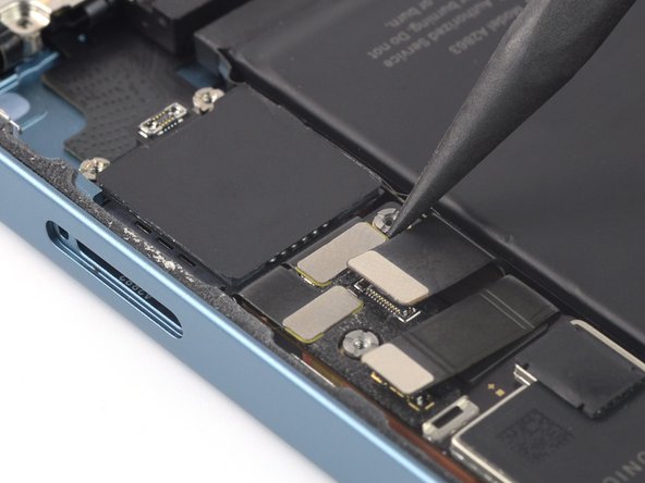
- Use the pointed end of a spudger to disconnect the battery cable by prying the connector straight up from its socket.
- Try not to damage the black silicone seal surrounding this and other board connections. These seals provide extra protection against water and dust intrusion.
- Bend the connector slightly away from the logic board to prevent it from accidentally making contact with the socket and providing power to the phone during your repair.
- Use a Y000 screwdriver to remove the single 1.0 mm-long screw securing the charging coil connector cover.
- Use a pair of tweezers to remove the charging coil connector cover.
- Use the pointed end of a spudger to disconnect the charging coil cable by prying the connector straight up from its socket.
- Remove the rear glass assembly.
- Apply new adhesive where it's necessary after cleaning the relevant areas with isopropyl alcohol (>90%).
- During reassembly, pause here if you wish to replace the rear glass adhesives.
- Use a Y000 screwdriver to remove the two 1.3 mm-long screws securing the front camera assembly cable bracket.
- Use a pair of tweezers or your fingers to remove the front camera assembly cable bracket.
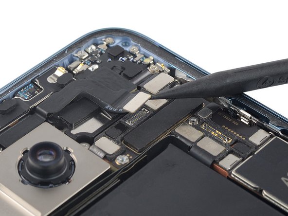
- Use a spudger to disconnect the camera and the sensor cables by prying the connectors straight up from their sockets.
- Use a pair of tweezers or your fingers to remove the front-facing camera and sensor assembly.
- The next two steps show how to remove an antenna that's in some models. If you don't have this antenna, skip these steps.
- Use a spudger to disconnect the antenna cable by prying the connector straight up from its socket.
- The antenna is lightly adhered to the earpiece speaker.
- Insert the tip of a spudger under the top left corner of the antenna.
- Pry up to separate the adhesive under the antenna.
- Remove the antenna
- Use a spudger to disconnect the earpiece cable by prying the connector straight up from its socket.
- Use a Phillips screwdriver to remove five 1.4 mm‑long screws securing the earpiece speaker.
- Use a Phillips screwdriver to remove the 1.1 mm‑long screw securing the earpiece speaker to the frame.
- Use a pair of tweezers or your fingers to remove the earpiece speaker.
- The top left edge of the earpiece speaker is equipped with a rubber gasket. During reassembly, make sure the gasket lines up with its recess in the frame correctly.
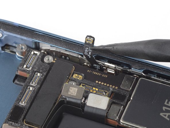
- Use a spudger to disconnect the power button connector cable by prying the connector straight up from the socket.
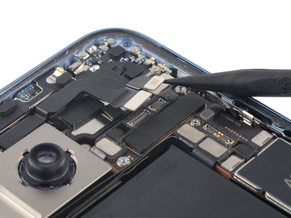
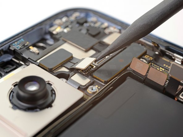
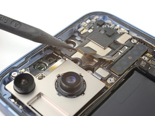
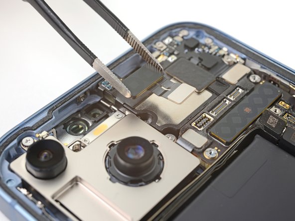
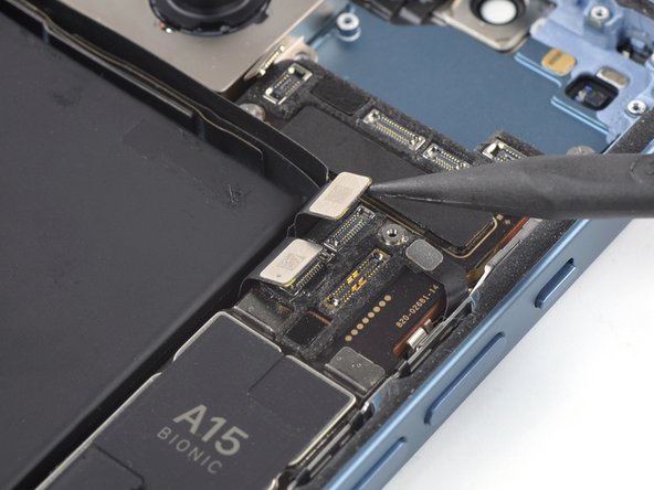
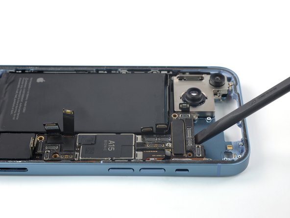
- Use a spudger to disconnect the two rear camera cables by prying the connectors straight up from their sockets.
- Use a spudger to disconnect the volume buttons connector cable by prying the connector straight up from the socket.
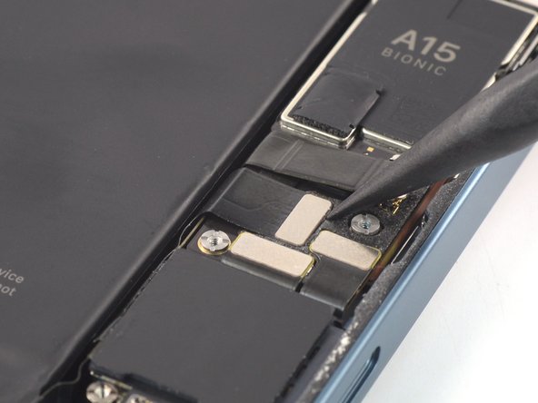
- Use a spudger to disconnect the SIM card reader and Taptic Engine cable by prying the connector straight up from the socket.
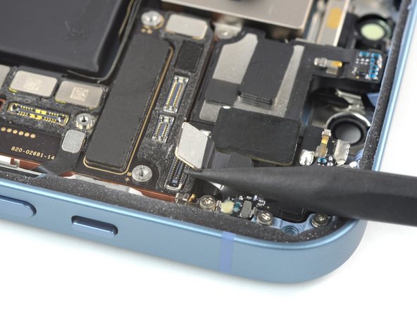
- Use a spudger to disconnect the lightning connector assembly cables by prying the connectors straight up from their sockets.
- Use a standoff driver to remove the five standoff screws.
- Four 3.7 mm-long standoff screws
- One 3.2 mm-long standoff screw
- Standoff screws are best removed using a dedicated standoff driver or driver bit. In a pinch, a small flathead screwdriver will do the job—but use extra caution to ensure it doesn't slip and damage surrounding components.
- Insert the flat end of a spudger underneath the top edge of the logic board.
- Pry up with the spudger to loosen the logic board.
- Use your fingers to remove the logic board.